TestProcedure(continued)
g417682
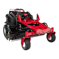
Figure31
LeftSide
1.Leftsidetractionpump3.Leftsidewheelmotor
2.Hydraulictube
4.Disconnectbothendsofthehydraulictubeandremovethetubefromthe
machine.
5.Installonehydraulictesthosetotheexposedttingatthetractionpump,and
asecondtesthosetotheexposedttingatthewheelmotor.
6.Installahydraulictestertotheexposedendsofthetesthoses.Makesure
thetesterisinstalledinthecorrectowdirection(towardthewheelmotor)
andthetesterowcontrolvalveisfullyopen.
7.Installtherearwheelandlowerthemachinetotheground.
8.Attachaheavychaintotherearofthemachineframeandanimmovable
objecttopreventthemachinefrommovingduringtesting.Removeasmuch
slackinthechainaspossible.
9.Disengagetheparkingbrake.
Note:Theenginewillstopifthebrakeisengagedandatractioncontrollever
ismovedoutoftheNEUTRALposition.
10.Starttheengineandrunitatlow-idlespeed.Correctanyhydraulicuidleaks
atthetestconnectionsbeforecontinuingthetest.
11.Setthethrottletothefullspeed(3,575to3,725RPM).Verifytheengine
RPMwithanon-contacttachometer.
12.Makesurehydraulicuidisatnormaloperatingtemperaturebyoperatingthe
machineforapproximately5minutes.
CAUTION
Useextremecautionwhenperformingthetest.Therearwheelbeing
testedwillbetryingtomovethemachineforward.
HydraulicSystem:TestingtheHydraulicSystem
Page5–28
FieldPro®6040
22267SLRevA
 Loading...