25
TRUE’S REMOTE SYSTEM - HOW IT WORKS
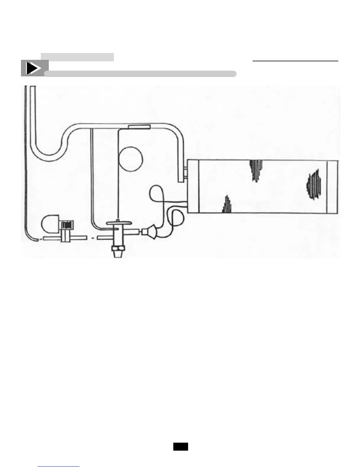
Refrigeration Schematic Diagram
Suction Line
TXV Bulb
Evaporator
Coil
Feeder
Tubes
Distributor
with Nozzle
Liquid Line
Solenoid
External
Equalizer
‘P’ Trap
Liquid and Suction
Tubing
TXV
The suction line will exit the evaporator coil as usual
for self-contained models, except it shall include an
Oil “P” trap. This is used to trap oil in low velocity
suction gases at a point just prior to a vertical rise.
Whether the compressor is to be located above or
below the evaporator, (True does not have control
over this), the suction will always have a “P” trap in
case the compressor is installed overhead.
The liquid line shall enter the cabinet and go direct-
ly to the liquid line solenoid, this is a normally
closed refrigerant valve which will be energized and
wired in series with the thermostat. When the ther-
mostat is closed (requires refrigeration) the solenoid
will be energized to open, allowing refrigerant to
pass to the “thermal expansion valve” (TXV). The
TXV allows refrigerant through to the evaporator
coil. If the evaporator has more than one circuit, a
distributor is used which evenly distributes refriger-
ant to each circuit. The TXV is made to open and
close by its sensing bulb which senses suction line
temperature on the other side of the evaporator. The
sensing bulb has the same refrigerant that is used in
the refrigeration system. When hot air passes over
the evaporator coil and warms the refrigerant, the
sensing bulb senses the warm condition and pushes
the sensing valve open. When too much refrigerant
flows into the evaporator, the sensing bulbs refriger-
ant cools and contracts allowing the diaphragm to
ease away the needle valve, thus closing the valve.
The external equalizer is another sensing element
which helps the sensing bulb to more accurately feed
refrigerant. The external equalizer line must be
down-stream of the TXV bulb. The TXV bulb
should be insulated with corktape.
 Loading...