73
REQUIRED TOOLS
• Drewel tool or sharp knife
• 3/4" hole saw
• Pop rivet tool
• 7/8" deep well socket
• Tape measure
• Phillips screw driver
• Slot screw driver
• #32 drill bit
INSTALLATION
___________ STEP 1 ___________
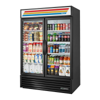
Use tape measure and mark a center
line at 34 3/4" down from the top of the
cabinet on the left end. Mark second
center line 7/8" from outside edge of
cabinet . This should locate the hole in
the end of the cabinet.
___________ STEP 2 ___________
Use 3/4" hole saw and drill hole on
center mark.
___________ STEP 3 ___________
Remove door jam gasket from left
door jam.
___________ STEP 4 ___________
Draw center line on black plastic fill
in. Align fill in center line with cabi-
net center line and mark a line along
top and bottom to fill in.
___________ STEP 5 ___________
Using drewel tool or sharp knife, cut
out black plastic breaker on marked
lines. Remove this section of breaker
c o m p l e t e l y. Some of the aluminum
wall will need to be removed to create a
l a r ge enough compartment to work in.
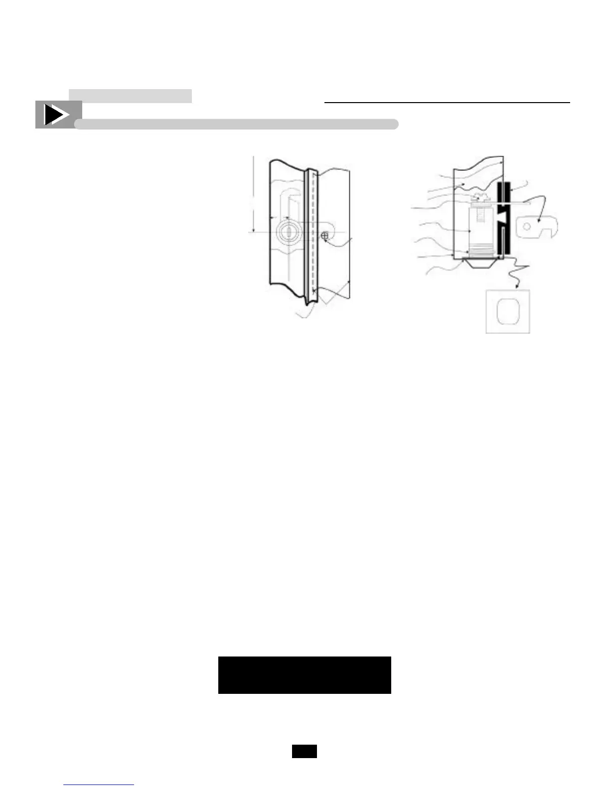
___________ STEP 6 ___________
Once the breaker is removed, now the
foam can be dug out to form the lock
box. Only enough foam should be
removed to install lock.
___________ STEP 7 ___________
Install lock assembly through 3/4"
hole. Place retainer plate and lock nut
end, tighten with 7/8" socket: Install
tumbler and latch assembly and tighten
screw.
___________ STEP 8 ___________
Install black plastic fill in plate work-
ing lock to make sure latch will move
through the slot. When components
operate properly, fasten fill in with
black pop rivets.
REMINDER
Remember to install left
door gasket
___________ STEP 9 ___________
With left door installed, mark rear of
door where the notch in the latch meet
the door frame. Drill a #32 hole on the
mark. Install screw and latch tube
assembly into drilled hole. Latch
should drop onto tube assembly and
lock left door.
___________ STEP 10 ___________
Install lock bar assembly to rear edge
of right door. Install so the bar is 2"
from the top of the door in the storage
position (use #32 drill bit).
___________ STEP 11 ___________
Lower bar into locking position. It
should be positioned against 3" break-
er strip. Install third SS clip so locking
bar will fall into it as a pocket. This
will hold bar in the locking position
(use #32 drill bit).
 Loading...