REQUIRED TOOLS
• 1/16" Drill
• 1/8" - 1/4" Shim (2)
• Socket wrench
____________ STEP 1 ____________
Remove all products and shelving from
interior of cabinet.
____________ STEP 2 ____________
Disconnect power to the unit.
____________ STEP 3 ____________
Wipe interior of cooler with a clean dry
cloth to remove dirt and moisture.
Surface must
be clean and
dry for adhe-
sive on extru-
sions (mirror
support strips).
____________ STEP 4 ____________
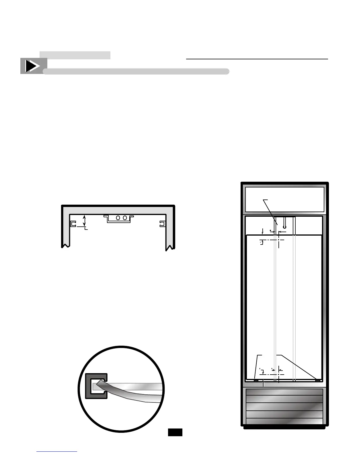
Measure 15/16" from rear interior wall for-
ward and mark the side wall for the mirror
support strip location. Select two shims of
equal height between 1/8" - 1/4 (one for
each side of the cabinet). Measure and
mark the height of the shim against the
side wall. Repeat on the opposite wall (see
figure 1 & 3).
____________ STEP 5 ____________
Locate two channel extrusions
(mirror support strips).
Remove paper strip cov-
ering adhesive from one
of the mirror support
strips.
____ STEP 6_____
Carefully secure mir-
ror support strip
against the side wall
the height of the shim
mark and along the mark
15/16" from the back wall.
Repeat on the opposite wall (adhesive
backing is the only anchor for the mirror
supports.
____________ STEP 7 ____________
Place shims on the interior floor in line to
support the mirror when in position.
____________ STEP 8 ____________
Slip one edge of the mirror in the mirror
support strip channel, bow mirror and
feed into the other mirror support strip.
Work until mirror fits flat inside support
strips and rests on top of the floor shims
(see figure 2).
____________ STEP 9 ____________
Locate left edge of
the drain line
cover at the rear of
the cabinet. At the
top edge of the
mirror measure in
1" and down 2".
Mark center point.
At the bottom
edge of the mirror measure in 1" from the
drain line cover and up 2" from the bottom
edge of the mirror. Mark center point. (see
figure 3).
NOTE
If the drain line cover edge at the tank
bottom is difficult to locate measure the
distance from the side wall to the center
point at the top of the mirror and use that
measurement for the bottom center point.
____________ STEP 10 ____________
Drill pilot holes at both center points
with a 1/16" drill bit through the
mirror and drain line cover.
______ STEP 11 _____
Fasten 10-16 x 1/2 hex
knurled head screw
(included) in both
pilot holes snug
against mirror.
WARNING
Do not over tighten screw to avoid
cracking mirror.
____________ STEP 12 ____________
Remove shims, replace shelving and
reconnect power to cabinet.
Figure 3.
shims
drain line cover
5/16”
1
2
2 1
Figure 2.
Figure 1.
INSTALLATION INSTRUCTION
GDM-23FC Mirror Retrofit Kit

 Loading...