43
INSTALLATION INSTRUCTION
TEMPERATURE CONTROL REPLACEMENT
(For Cabinets With Larger Than 1/3 H.P. Compressors)
Accessing Wire Connections:
A. Remove ballast box cover by backing out two hex head screws.
(See Figure 2).
NOTE: Wiring diagram is positioned on inside cover.
WARNING:
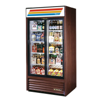
(Swing Door)
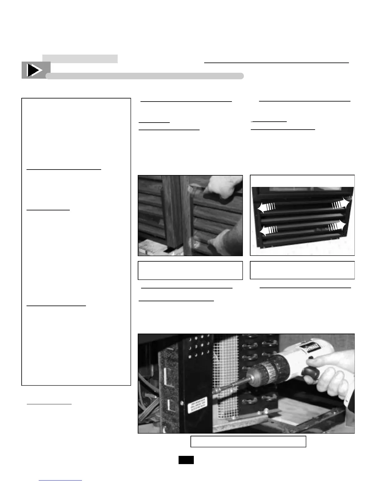
Remove Louvered Grill:
A. Remove screws as indicated by
arrows.
___________ STEP 1 ___________
Removing Power:
A. Disconnect power to the unit.
Figure 1. Removing louvered grill
Figure 2. Removing ballast box cover
Failure to disconnect power to
the unit may result in
electrocution to field personnel.
Qualified Repair Personnel:
These repairs should be performed
by a qualified service technician.
Required Tools:
• Phillips-head Bit
• 1/4” Nut Driver Bit
• Wire Cutters
• Drill
• Needle-Nose Pliers
• Wire Strippers
• Crimping Tool
• Voltmeter
• Plastic Mallet or Hammer
• Slotted Screw Driver
Figure 1A. Removing louvered grill
(swing door model)
Contents of Relay Kit:
• Relay (and mounting screws)
• Relay Shield (and mounting screws)
• (4) Relay wires: 2 blacks, 1 pink,
1 white with insulated female spade
connectors on one end.
• Grommet
• (4) Sta-con connectors
• New temperature control
• Instructions
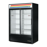
(Slide Door)
Remove Louvered Grill:
A. To remove grill, loosen upper
screw on each end of grill and
remove lower screws. Gently swing
grill forward and up.
STEP 2
STEP 3
 Loading...