52
LOCATING POWER CORD
WIRING FOR CUTTING (cont.)
____________ ...STEP 6 ____________
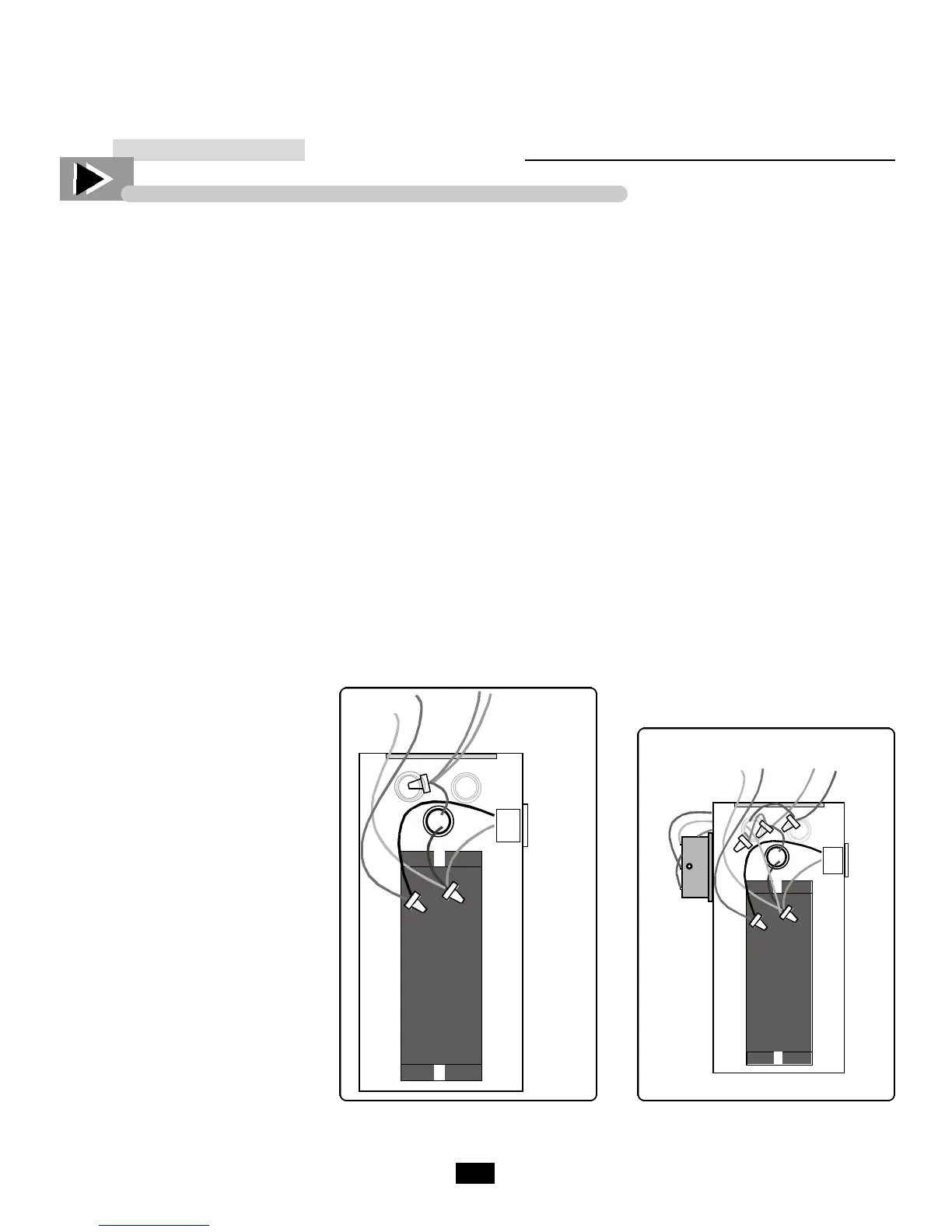
Locate the junction of tan, pink and black
wires coming from power cord area. See
figure 1 and Figure 2. If cabinet is sup-
plied with a European style cord, the
power cord, black, wire will be brown.
At this junction, cut the pink wire several
inches from the junction. Strip each end of
wire 1/2". See figure 2.
ATTACHING THE SURGE
PROTECTOR TO THE BALLAST BOX
____________ STEP 7 ____________
Position the surge protector on left side of
ballast box toward back edge. Allow for
cover clearance. See Figure 1. # 7
Using self-drilling screws, attach the surge
protector on the ballast box,
as illustrated in Figure 1, step # 7.
NOTE
For GDM-23 mount surge protector
below flooring.
SPLICING INTERCONNECTI N G
WIRING TO SURGE PROTECTO R
____________ STEP 8 ____________
a. Route all interconnecting wires
through newly created knockout hole.
See Figure 2.
b. Take one pre-cut 15" pink wire, and
locating pink wire still connected to
wire junction , connect these together
with an in-line splice or butt splice.
On surge protector, connect another
end of pink wire to "LINE IN",
(marked on surge protector).
c. Next, locate other loose pink wire in
ballast box, connect the remaining
pink wire with in-line splice or butt
connector.
d. On surge protector, connect other end
of pink wire to "LINE OUT".
e. Now create a 15" long white wire.
Strip both ends 1/2". On one end put
1/4" quick-connect insulated slip on
connector.
f. Locate junction of white wires in bal-
last box. (if cabinet is supplied with a
European style cord, this wire will be
blue.)
g. Cut end connector off junction, re-
strip wires and add white wire. Re-
crimp the connection using a large
closed-end connector.
h. On surge protector, connect other end
of white wire to "NEUTRAL".
ENCLOSING WIRING AND UNIT
START-UP
____________ STEP 9 ____________
a. Neatly replace wires into ballast box
and replace lid.
b. Plug in cabinet. Green light on surge
protector should be "off".
c. Cabinet now has power. There will
be a 3 minute delay before the pump
will start.
d. Test voltage.
d. After start-up delay, cabinet should
operate normally.
e. Replace louvered grill cover and
secure with four phillips-head screws.
Check all wiring to make sure it is correct. Connections should be verified against Figures 3 and 4.

 Loading...