INSTALLATION INSTRUCTION
Lock Installation - GDM - model 23/26 single swing door
REQUIRED TOOLS
• tape measure
• 1/4" drill
• 2" saw drill hole saw
• 3/4" saw drill hole saw
• straightedge
• tin snips
• Phillips screwdriver
• file
• drill bit for screws on lock cup
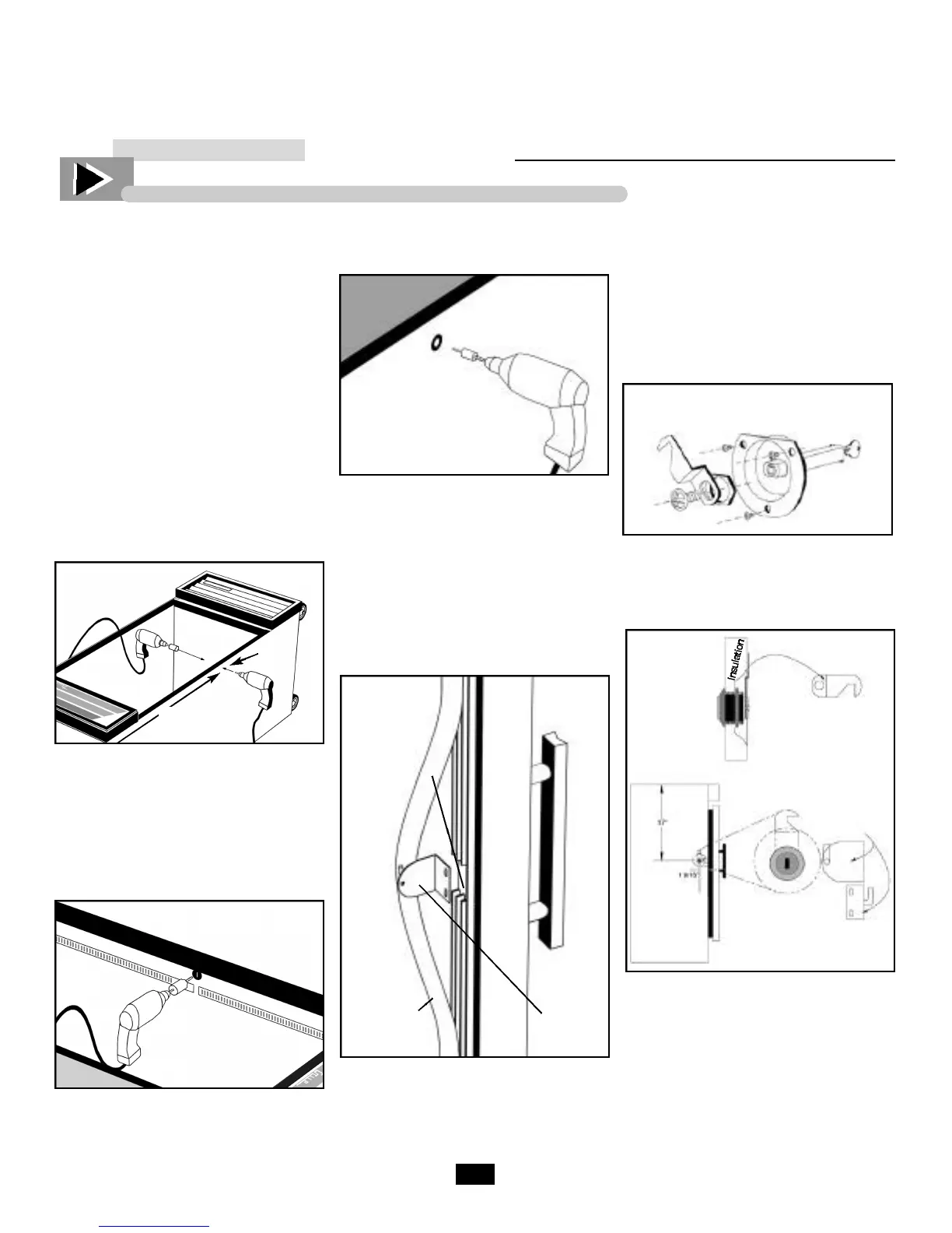
___________ STEP 1 ___________
Drill 1/4" pilot hole 37" from the top of
the cooler and 1 9/16" down from end
panel edge. Pierce through wall
thickness and then rock slightly to create
a vertical slot approximately 1/2".
___________ STEP 2 ___________
Using a 2" hole saw, insert drill into
existing hole and align top of bit with
the coolers black tank plastic. Drill far
enough to pierce the interior skin (stop
at the insulation).
___________ STEP 3 ___________
Insert 3/4" hole saw into original, exte-
rior pilot hole, and drill through
insulation. Remove insulation from
created hole and smooth burs with a
file.
___________ STEP 4 ___________
Using straightedge, pencil mark a
straight line, parallel to the lock cup
knockout opening. With tin snips, trim
off top of lock cup.
___________ STEP 5 ___________
Insert lock cup into drilled opening
(interior wall), while inserting lock
assembly from the exterior wall. Fasten
assembly by attaching hex nut. A n c h o r
lock cup with three self-tapping screws.
___________ STEP 6 ___________
Install latch and secure with phillips
washer head screw.
___________ STEP 7 ___________
Pull gasket away from door trim.
Using masking tape as a center point.
Score interior door trim using the lock
to measure top and bottom width.
With tin snips, cutaway door trim in
order to accommodate lock plate.
Note:
Other single swing door
cabinets please consult True
Manufacturing Technical
Service at 800-325-6152.
Lock
Plate
Gasket
Lock
Assembly
1
9
/
1 6
˝
37˝
Inside of
Cooler
Trimmed with
Tin Snips
Lock
assembly
(exploded view)
Cabinet
Side View
Latch front
view
Front
view
Lock plate
Outside of
Cooler
 Loading...