76
REQUIRED TOOLS
• Tape Measure
• 1/4” Drill
• 2” Saw Drill Hole Saw
• 3/4” Saw Drill Hole Saw
• Straight Edge
• Tin Snips
• Phillips Screw Driver
• File
• Drill Bit For Screws on Lock Cup
FIRST...
Before beginning installation, remove
front shelf standard from interior wall
on handle side of cabinet.
INSTALLATION
___________ STEP 1 ___________
Drill 3/4" hole on outer cooler wall of
foam. (Do not penetrate inner wall).
(See diagram) Center point of hole is
2 1/4" from front of cooler (including
plastic trim) and 13 3/8" from bottom
of cooler.
___________ STEP 2 ___________
Drill 2" hole on inner cooler wall, cen-
tered over 3/4" hole. Drill just deep
enough to accommodate white-metal
backing plate.
CAUTION
Do Not Drill Too Deep.
___________ STEP 3 ___________
Remove insulation so white-metal
backing plate will fit in hole.
___________ STEP 4 ___________
Check fit of locking cylinder after
inserting through the outer cooler wall.
Fill any air space around cylinder and
plate with insulation.
___________ STEP 5 ___________
Place white-metal backing plate over
locking cylinder, into 2" hole. Attach
lock nut to secure cylinder. Drill holes
and attach white metal backing plate to
inner cooler wall. (this can be done
with screws or pop rivets your option.
Parts not provided.)
___________ STEP 6 ___________
Attach lock arm to locking cylinder
with 1/2" screw (provided). Ti g h t e n
lock nut and screw. Locking mecha-
nism on cooler wall should now be
complete. Check operation.
___________ STEP 7 ___________
Remove rubber gasket from plastic
door channel.
___________ STEP 8 ___________
Determine proper height for strike
plate extension to be engaged by lock-
arm. Then determine location for two
drill holes to attach strike plate to door
frame. Drill two 3/16" holes for strike
plate through door frame and inner-
most plastic channel. (CAUTION:
Make sure strike plate is positioned on
the door so when the door is closed it
will pass as close to the edge of the
opening as possible without hitting.)
___________ STEP 9 ___________
Remove portion of the plastic channel
wall where the strike plate will be
located.
___________ STEP 10 ___________
Securely attach strike plate to metal
frame (through plastic channel) with
3/4" screws (provided).
___________ STEP 11 ___________
Replace rubber gasket in plastic door
channel.
___________ STEP 12 ___________
Check for proper operation.
___________ STEP 13 ___________
Install split standard (2 pieces) in place
of original one piece standard. Use
original mounting holes and secure.
NOTE
Shorter piece should be at top.
INSTALLATION INSTRUCTION
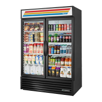
LOCK INSTALLATION (GDM -5 & GDM-5PT swing door models)

 Loading...