44
INSTALLATION INSTRUCTION
TEMPERATURE CONTROL REPLACEMENT CONTINUED.......
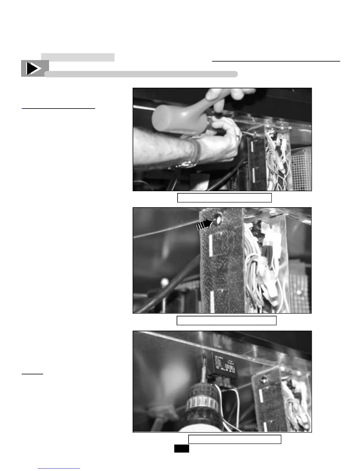
Figure 3. Driving out knockout
Figure 4. Installing the grommet
Figure 5. Anchoring relay
*Grommet
___________ STEP 4 ___________
Relay Connection Mounting:
A. With slotted screw driver and
plastic mallet or hammer, drive out
knock out positioned on left side of
ballast box. (See Figure 3).
B. Install the supplied grommet*
into the knockout hole. (See Figure 4).
C. Mount relay to underside of
unit on the left side of ballast box,
and 3/4” back from the front edge
of the underside.
NOTE: Mount relay next to the
ballast box, so that when the relay
shield is installed it covers the relay
and all exposed wiring.
Relay should be anchored with two
self-tapping screws, (supplied in kit),
as pictured in Figure 5.
*Grommet

 Loading...