11.D/A CONVERTER
92
11-1-1. Obtaining Voltage Output Signal
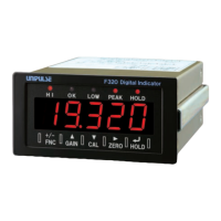
Use the + and - terminals of the F320 for connection with an external device
(2kΩ or more load resistance).
11-1-2. Setting of D/A Zero and Gain
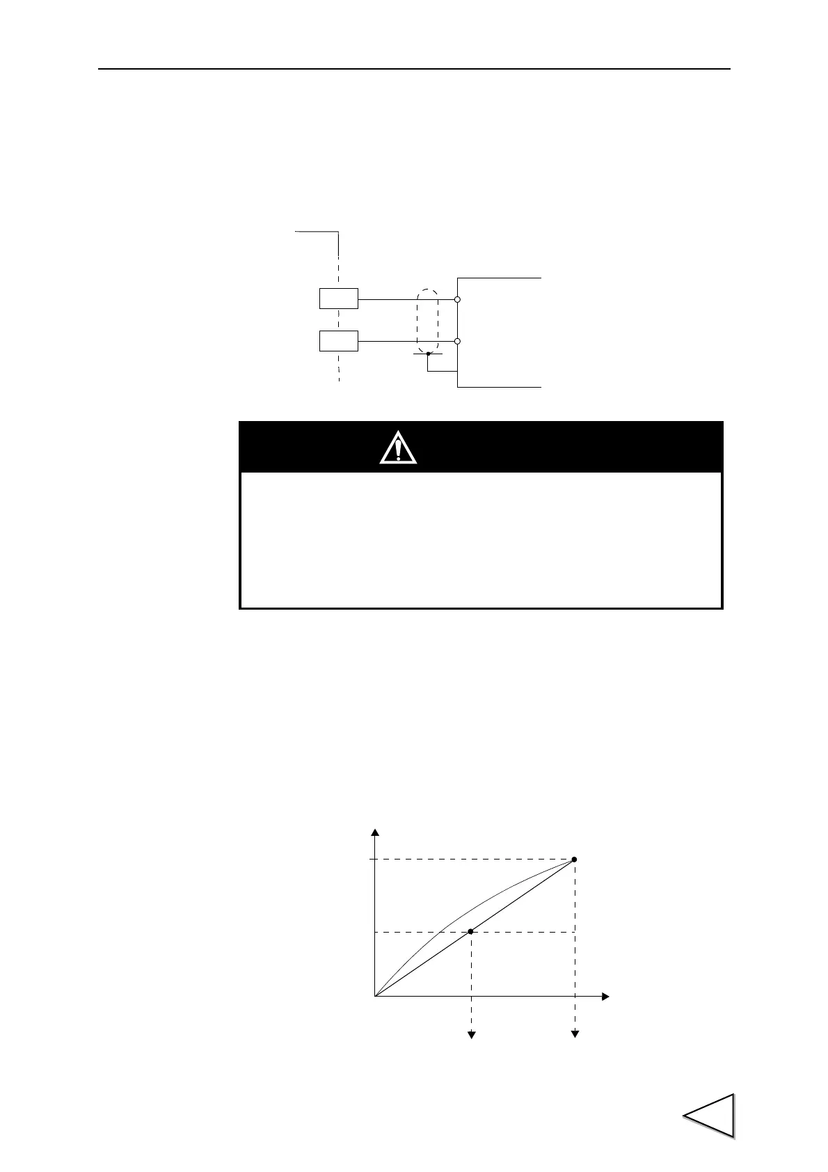
With the D/A converter of the F320, an analog output is obtained by setting the
indicated value to output 0V (D/A zero set value) and the indicated value to
output 10V (D/A full scale set value). Respective set values are inputted by the
D/A zero and full scale setting functions.
+
-
+
-
External device
Load resistance
2kΩ or more
SIG
GND
← Inside Outside →
F320
CAUTION
• The D/A converter voltage output is an option.
• Do not apply external voltages. Breakage will result.
• Do not short-circuit the voltage output. Doing so will cause a failure.
Also, connecting a capacity load may cause oscillation.
Voltage
(V)
10
-10
Indicated value
0
Resolution 1/10000
D/A full scale set valueD/A zero set value