Home
Unipulse
Measuring Instruments
F320
Page 75 (HOLD Key Valid; Invalid)
Unipulse F320 - HOLD Key Valid; Invalid
129 pages
Manual
Save Page as PDF
To Next Page
To Next Page
To Previous Page
To Previous Page
Loading...
6.SETTING OF FUNCTIONS
61
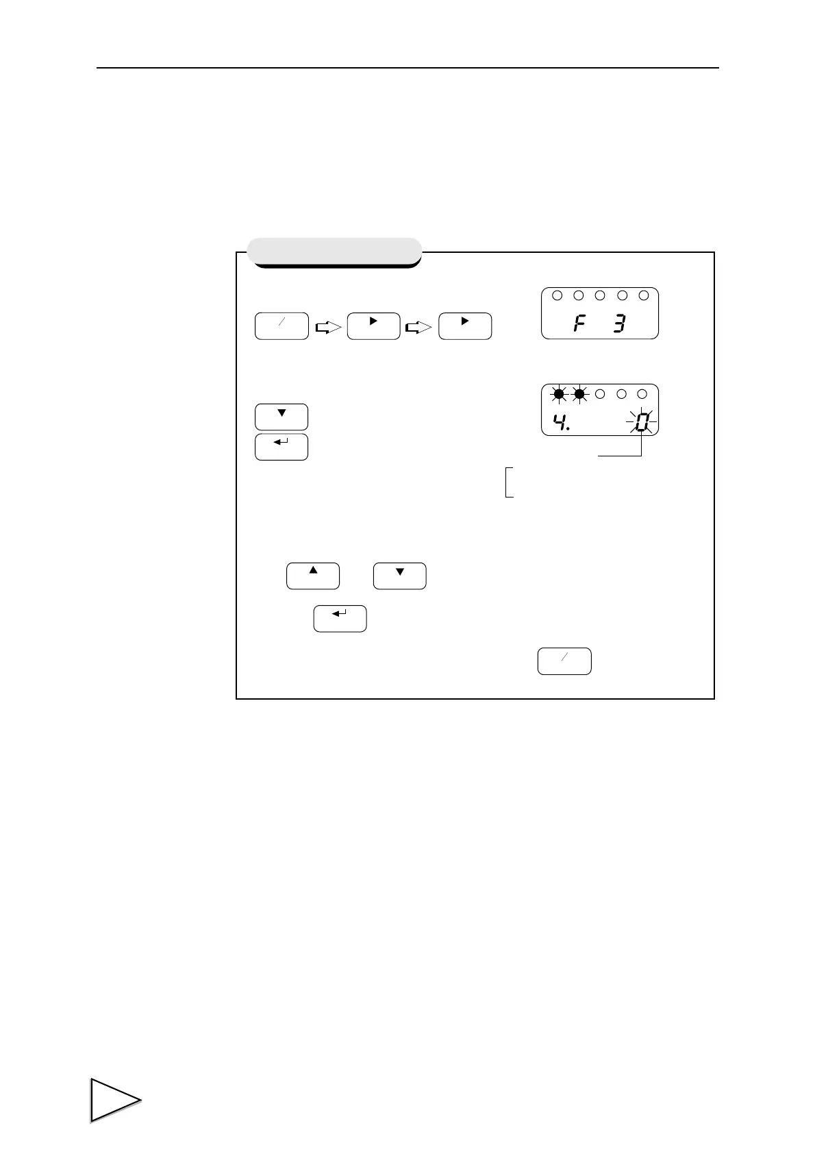
6-14. HOLD Key V
alid / Invalid
This function validates/invalidates the operation of the HOLD key
.
1)
Select setting mode 3.
2)
Select hold key valid / invalid
Use
and
keys to set the hold key valid / invalid,
then use
key to va
lidate the setting.
T
o return to the indicated value display
, press
key
.
FNC
+
-
ZERO
ZERO
Press four times.
HOLD
CAL
GAIN
CAL
HOLD
FNC
+
-
HOLD Key V
alid / Invalid
Hold Key Operation
1 : Invalid
0 : V
alid
74
76
Table of Contents
Main Page
Default Chapter
10
Table of Contents
10
1 Functional Descriptions
15
Front Panel
15
1-1-1Status Display
15
1-1-2Numerical Display
15
1-1-3Setting Key Pad
17
Rear Panel
19
1-2-1Protective Ground
19
1-2-2Frame Ground (Frame Terminal)
19
1-2-3Options Slot
19
1-2-4AC Power Input Terminal Block
20
1-2-5Signal Input/Output Terminal Block
20
2 Installing in a Control Panel
22
3 .Connection
23
Connecting Strain Gauge Sensor
24
Connecting Power Input Terminal
26
3-2-1AC Spec
26
3-2-2DC Spec. ( Depending on the Request at the Time of Order )
29
Connecting High / Low Limit Relays
32
Connecting Hold and Digital Zero Signals
33
Connecting Analog Monitor Output (VOL OUT)
34
4 .Setting Mode Configuration
35
Selection of Setting Items
35
Display of Setting Items
37
List of Values
39
Setting Procedure
42
5 .Calibration
43
Equivalent Input Calibration Procedure
44
Actual Load Calibration
50
6 .Setting of Functions
56
High /Low Limit Value
56
High / Low Limit Comparison Mode
59
Hysteresis
60
Digital Offset
63
Near Zero
64
Digital Filter
65
Analog Filter
66
Motion Detect
67
Zero Tracking
69
Hold Mode
71
Set Value LOCK
72
Calibration LOCK
73
ZERO Key Valid / Invalid
74
HOLD Key Valid / Invalid
75
Scale Division
76
Display Frequency
77
Decimal Place
78
Excitation Voltage
79
7 Hold Function
80
Peak Hold
80
Sample Hold
82
8 .Digital Zero Function
84
9 .Rs-485 Interface
85
(Communication Protocol; Modbus-RTU)
85
Communication Specifications
85
9-1-1Standards
85
9-1-2Data Address
86
Connecting RS-485
87
9-2-1One-To-One Connection
87
9-2-2Multiple Connection
87
9-2-3RS-485 Communication Method
88
9-2-4Rs-485 ID
89
9-2-5RS-485 Transmission Delay Time
90
10 .Bcd Data Output
91
BCD Data Update Rate Selection
92
Sink Type (BCO Option)
93
10-2-1Equivalent Circuit
94
10-2-2Connector Pin Assignment
96
Source Type (BSC Option)
99
10-3-1Equivalent Circuit
100
10-3-2Connector Pin Assignment
102
11 .D/A Converter
105
Voltage Output (DAV Option)
105
11-1-1Obtaining Voltage Output Signal
106
11-1-2Setting of D/A Zero and Gain
106
11-1-3About D/A Resolution
107
Current Output (DAI Option)
108
11-2-1Obtaining Current Output Signal
109
11-2-2Setting of D/A Zero and Gain
109
11-2-3About D/A Resolution
110
D/A Zero and Full Scale
111
D/A Output Mode
112
13 .Overscale/Error Displays
114
Overscale Display
114
Calibration Error Display
114
14 .Self-Check Function and Initialization
115
Self-Check
115
Initialization
117
F320 Block Diagram
119
15 .DIMENSIONS (Standard)
120
Dimensions (When the BCO Option Is Equipped)
121
Dimensions (When the DAV/DAI Option Is Equipped)
122
16 .Specifications
123
Analog Section
123
Indicator Section
124
Setting Section
124
External Signals
125
Interface
125
General Specifications
128
Accessories
128
Related product manuals
Unipulse F325
160 pages
Unipulse F701+
149 pages