16.SPECIFICATIONS
110
16-2. Indicator Section
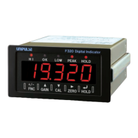
Indicator Numerical display (5-digit),
15mm in character height, by 7-segment red LED
Numeric 5digits ±
(“ ” or nothing is displayed at the
high order position of the indicator.)
Indicatid value -19999 to 19999
Decimal point The display position is selectable.
88.888, 888.88, 8888.8, 88888
Items Status HI, OK, LOW, PEAK, HOLD
Red LED 5
Count 3, 6, 13, 25times/sec. Selectable
16-3. Setting Section
Key switch
Items Calibration:Zero/Span calibration(actual load calibration,
equivalent input calibration)
<Setting mode 1>
High limit value, Low limit value, High/Low limit comparison
mode, Hysteresis, Digital offset, Near zero
<Setting mode 2>
Digital filter, Analogfilter, Motion detect(time),
Motion detect(range), Zero tracking(time),
Zero tracking(range),Hold mode
<Setting mode 3>
Set value LOCK, Calibration LOCK, ZERO key valid/invalid,
HOLD key valid/invalid, Scale division, Display frequency,
Decimal place, Excitation voltage
<Setting mode 4>
RS-485 communication method, RS-485 ID,
RS-485 transmission delay time, BCD data update rate,
D/A zero setting, D/A full scale setting , D/A output mode,
Password
FNCGAINCALZEROHOLD
(5key)
(+/-) (▲) (▼) ( ) ( )
▲