6.SETTING OF FUNCTIONS
43
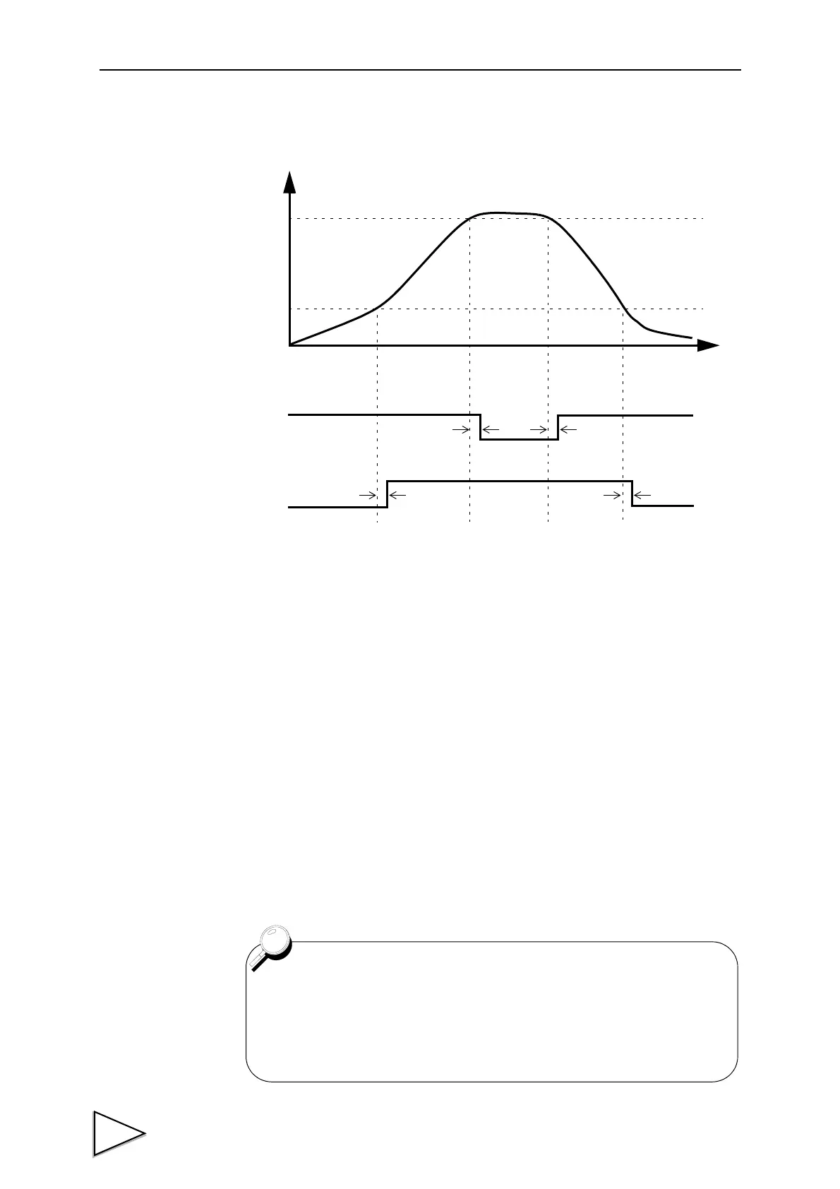
• Timing Chart
t1 : Time from when the indicated value exceeds the high limit set value to
when the relay turns ON
t2 : Time from when the indicated value becomes the high limit set value or
less to when the relay turns OFF
t3 : Time from when the indicated value becomes the low limit set value or
more to when the relay turns OFF
t4 : Time from when the indicated value falls below the low limit set value to
when the relay turns ON
Time
Indicated value
High limit value
Low limit value
HI
LOW
OFF
ON
OFF
ON
t1 t2
t3 t4
t1 to t4: MAX 15mS (relay operating time: MAX 10mS)
• To prevent the relay from chattering, hysteresis can be set.
For details, see “Hysteresis” on page 46 .
• For the connection of the high/low limit relay output terminals, see
“Connecting High/Low Limit Relays” on page 18 .