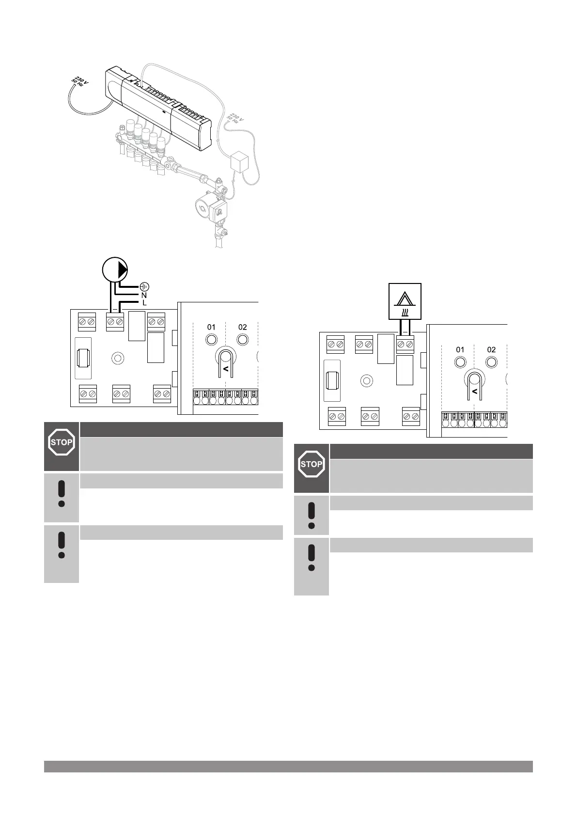
Circulation pump
Warning!
Risk of electrical shock! Electrical installation and service
behind secured 230 V AC covers must be carried out
under the supervision of a qualified electrician.
Note
See the documentation from the circulation pump
supplier as well as relevant Uponor wiring diagrams
before connecting the pump.
Note
There is no power in the room controller to supply the
pump. The connector in the room controller provides only
a dry contact to switch off and on the power connection
to the pump.
1. Ensure that the power is disconnected from both the room
controller and the circulation pump.
2. Remove the screw and open the cover for the optional
connections compartment.
3. Route the cable to/from the pump via a cable entry.
4. Connect the L wire to/from the pump via the connection labelled
Relay 1 (PUMP).
5. Secure the pump cable with a cable clamp in the enclosure.
6. Close and secure the lid to the optional connections
compartment.
Relay function
The room controller start the circulation pump (relay closed) when
there is a demand for heating or cooling.
If a communication module is connected and multiple room
controllers are used the relay can be set to individal or common
pump mode.
Individual pump:
Relay function is set on a room controller basis. One circulation pump
per room controller is connected to relay 1. When there is a demand
to a specific room controller, only the pump connected to that room
controller is started.
Common pump:
Relay function is set on a system wide basis. One pump per system
is connected (to the master room controller relay 1 only). When there
is a demand somewhere in the system, the main pump is started.
When set to Common, the circulation pump relay can be used for
other functions on the sub room controller. See room controller relays
for more information.
Boiler
RELAY 2 (BOILER)
WD0000004
Warning!
Risk of electrical shock! Electrical installation and service
behind secured 230 V AC covers must be carried out
under the supervision of a qualified electrician.
Note
This connection requires a dry contact sensing input in
the boiler.
Note
There is no power in the room controller to supply the
boiler. The boiler connector in the room controller
provides only a dry contact to switch on and off the power
connection to the boiler.
1. Ensure that the power is disconnected from both the room
controller and the boiler.
2. Remove the screw and open the cover for the optional
connections compartment.
3. Route the cable from/to the boiler via a cable entry.
4. Connect the boiler to the connection labelled Relay 2 (BOILER).
5. Secure the cable to/from the boiler with a cable clamp in the
enclosure.
6. Close and secure the lid to the optional connections
compartment.
Uponor Smatrix Wave PULSE
|
Installation and operation manual
|
29

 Loading...