EasyManuals Logo

Vacon 100 flow Installation Manual

Vacon 100 flow
128 pages
To Next Page IconTo Next Page
To Previous Page IconTo Previous Page
Page #68 background imageLoading...
Page #68 background image
8 Make sure that the grounding conductor is
connected to the motor and also to the terminals
that are identified with
.
a)
To obey the requirements of the standard
EN61800-5-1, obey the instructions in chapter
2.4 Grounding and earth fault protection.
A
C
D
B
Max. 70 Nm (620 lb-in)
20°
+/-5°
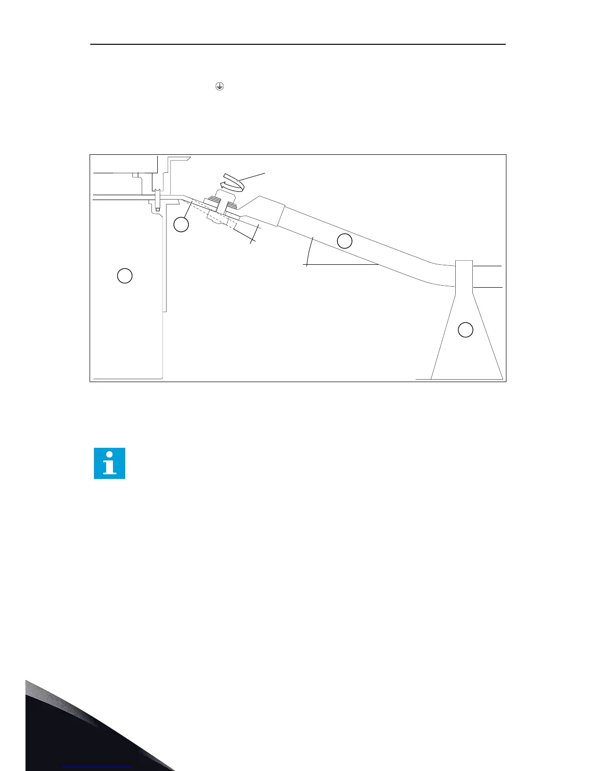
Fig. 24: Mechanical support for cables when the drive does not have the options module
A. The AC drive
B. The connection busbar. Terminals L1,
L2, L3, U/T1, V/T2, W/T3.
C. The power cable
D. The cable support
NOTE!
You must make sure that creepage and air distances are sufficient in your
installation and that they agree with the local regulations.
VACON · 68 POWER CABLING
6
LOCAL CONTACTS: HTTP://DRIVES.DANFOSS.COM/DANFOSS-DRIVES/LOCAL-CONTACTS/

Table of Contents

Other manuals for Vacon 100 flow

Questions and Answers:

Question and Answer IconNeed help?

Do you have a question about the Vacon 100 flow and is the answer not in the manual?

Vacon 100 flow Specifications

General IconGeneral
Protection classIP20
Communication interfaceRS-485
Operating temperature-10°C to +50°C
Storage temperature-40°C to +70°C
Ambient temperature-10°C to +40°C
Control methodSensorless vector control
Communication protocolsCANopen
ApprovalsCE, UL
I/O2 analog inputs
Protection featuresOvercurrent, overvoltage, undervoltage, overtemperature
Frequency range0 Hz to 400 Hz
Humidity5% to 95%, non-condensing
Voltage range208-240 V

Related product manuals