MCP-4J Quick Start Guide IS0368
Valco Melton4
To install a wheel-driven encoder:
1. Mount the encoder’s bracket to the frame of the parent
machine.
2. Ensure that the wheel of the encoder rides securely
against the belt and does not slip.
3. In the level-4 menu screen, set ratio compensation to
100 pulses.
Mounting the Encoder
An encoder must be installed in order for the control to determine the
speed of the parent machine. For best results, 100 pulses per inch
(25.4 mm) of product travel should be supplied to the VC3500. If less
than 100 pulses per inch (25.4 mm) are supplied, poor resolution
may result in pattern placement errors. If more than 100 pulses per
inch (25.4 mm) are supplied, the maximum specified speed of 2000
feet/min (610 m/min) must be reduced.
There are two primary types of encoders:
• Wheel-driven encoder
• Gear-driven encoder
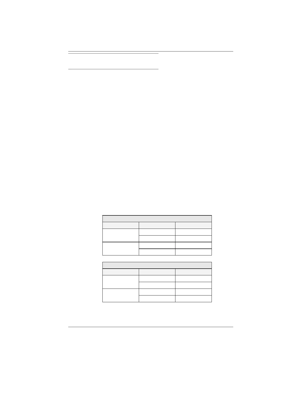
Red Encoder Wheel
Pulses Setup Circumference
1000
Metric 250 mm
Imperial 9.84 inches
500
Metric 250 mm
Imperial 9.84 inches
Black Encoder Wheel
Pulses Setup Circumference
1000
Metric 254 mm
Imperial 10.0 inches
500
Metric 254 mm
Imperial 10.0 inches
 Loading...