MC122 - MCP-4J Control Unit Section 3 - Basic features
29
Encoder Installation
Mechanical Installation of Encoder
An encoder must be installed in order for the control to determine the speed of the parent machine. For best results,
100 pulses per inch (25.4 mm) of product travel should be supplied to the VC3500. If less than 100 pulses per inch
(25.4 mm) are supplied, poor resolution may result in pattern placement errors. If more than 100 pulses per inch (25.4
mm) are supplied, the maximum specified speed of 2000 feet/min (610 m/min) must be reduced.
There are two primary types of encoders:
• Wheel-driven encoder
• Gear-driven encoder
Wheel-Driven Encoder
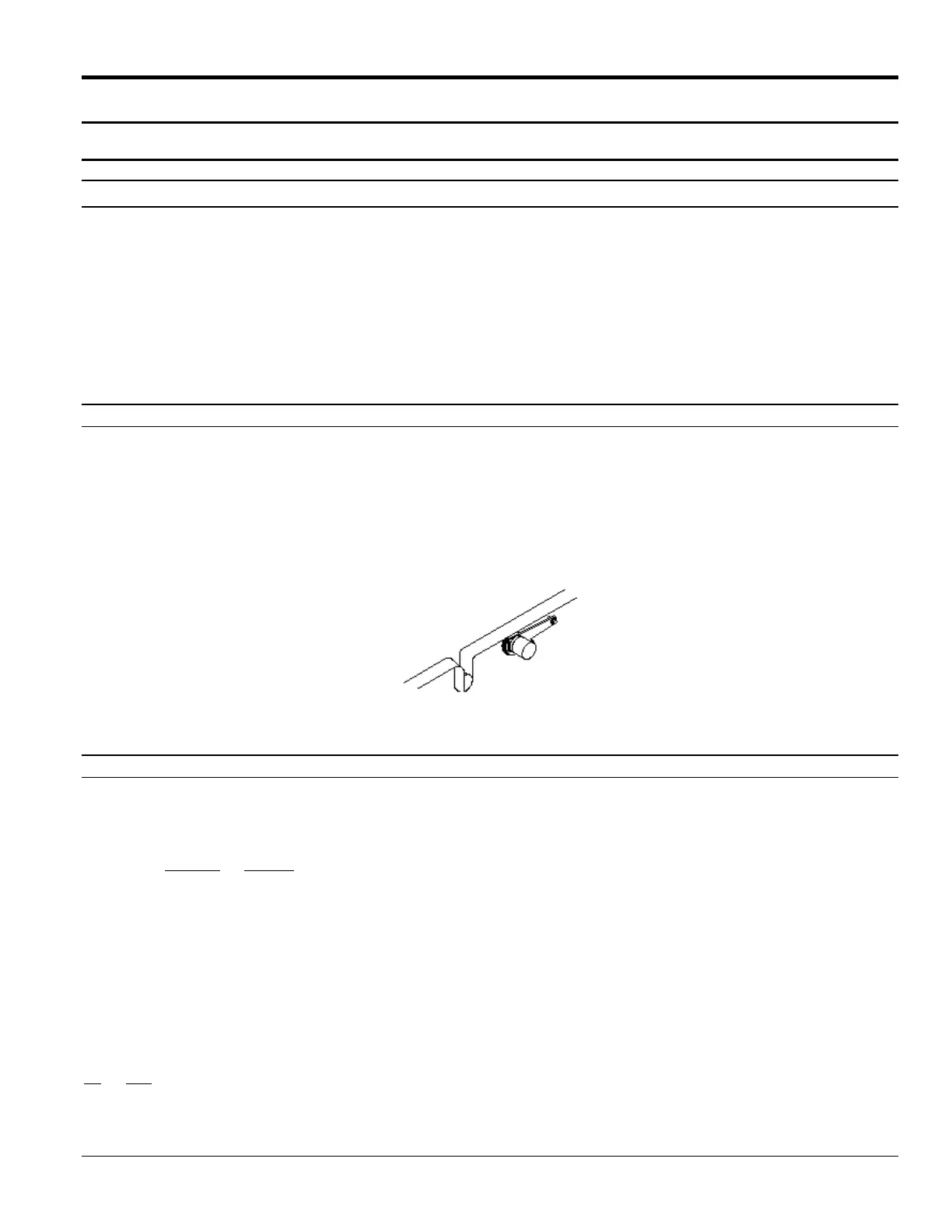
If using a wheel-driven encoder (Figure 5-6), a VDD-1000 encoder with a 10-inch measuring wheel is recommended.
To install a wheel-driven encoder, follow these steps:
1. Mount the encoder’s bracket to the frame of the parent machine.
2. Ensure that the wheel of the encoder rides securely against the belt and does not slip.
3. In the level-4 menu screen, set ratio compensation to 100 pulses.
Figure 3-17. Example of a Wheel-Driven Encoder
Gear-Driven Encoder
The following formula can be used to determine the correct combination of gear teeth and encoder for approximately
100 pulse per inch (25.4 mm):
Teeth-S x Counts = Pulses per inch (25.4 mm) of travel
Teeth-E Travel
Teeth-S = Number of teeth on the line-shaft driver gear
Teeth-E = Number of teeth on the encoder driven gear
Counts = Number of encoder pulses per revolution
Travel = Product travel in inches (or millimeters divided by 25.4)
per revolution of the drive shaft
Example:
Using a 92-tooth split line shaft gear (driver), a 24-tooth encoder driven gear, a 500-pulse encoder, and 18 inches (or
457 millimeters divided by 25.4) of travel per drive shaft revolution.
92 x 500 = 106.48
24 18
Therefore, the ratio compensation setting should be 106.5.
Gear-Driven Encoder - Continued
 Loading...