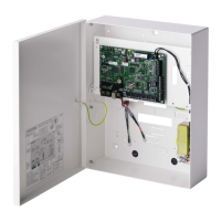
Installation & Configuration Manual
Add a Calendar Exception Day
Edit a Calendar Exception Day
Delete a Calendar Exception Day
Get the status of the Ethernet
Get the status of a modem
Get the log for a ARC receiver
Get the status of a FlexC ATS
Get the Network Log for a FlexC ATS
Get the Event Log for a FlexC ATS
Get the log for a FlexC ATP
Get the Network log for a FlexC ATP
Export a FlexC ATS configuration file
Import a FlexC ATS configuration file
Delete a FlexC Event Profile
Delete a FlexC Command Profile
Request a testcall for a FlexC ATP
Get the Configuration for a Door
Read the Status for a Door
Get the Status of a Verification Zone
Get the data for a Verification Zone
Send data to a Verification Zone
Upgrade the Panel Firmware
Upgrade Peripheral Firmware
Saves the Panel Configuration
Get Headers of Configuration Files
Get Language Configuration
Get Intruder Configuration
Get Status of X-BUS Devices
Get the Area Configuration
 Loading...


