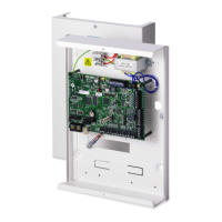
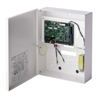
Mounting system equipment
Installation & Configuration Manual
Shelf separating battery compartment
6.3.1 Tamper protection
The tamper switch and back tamper bracket are fitted to the housing. The switch is
used on its own for front tamper purposes only or used with the back tamper
bracket for both front and back tamper protection. Either back or front tamper
protection is required depending on local approval.
The tamper bracket is held firmly in place with a securing screw. Remember to
remove this screw if commissioning the system for back tamper protection. Do not
remove this screw if using front tamper only.
6.3.2 Mounting the housing with tamper protection
To mount the housing:
1. Using the supplied mounting template, mark the 4 drill positions for fixing the
housing to the wall.
2. Drill and install suitable screws (see enclosed template) into the wall. Leave the
screws protruding 1.5cm from the wall.
3. The G5 housing is pre-configured for front tamper only. To configure the
housing for both front and back tamper, remove the front tamper securing
screw (item 1).
The tamper bracket swings to the far right of the orientation slot (item 6).

 Loading...


