EasyManuals Logo

Vanderbilt SPC42 Series User Manual

Vanderbilt SPC42 Series
402 pages
To Next Page IconTo Next Page
To Previous Page IconTo Previous Page
Page #69 background imageLoading...
Page #69 background image
Number Name Description
2 SPC status
LEDs
These 7 LEDs display the status of various system parameters as described in Controller
status LEDs on page362.
3 AC power
input
A/C Mains Input:
The mains AC input voltage is applied to this 2-pin connection via a transformer
contained in the SPC housing. The earth lead from the mains supply is wired to a
connection point on the metal housing.
Clock Reference*:
A clock reference signal can also be applied to this 2-pin connector to maintain accurate
system time.
4 Reset
button
l To reset the controller:
– Press this switch once.
l To reset the programming settings to default and reboot the controller:
– Hold down the button until you are asked if a factory reset is desired.
– Select YES to reset to factory defaults.
Warning: Defaulting the controller to factory settings deletes all configuration files,
including backups, stored on the controller. All isolates and inhibits are also deleted. It is
recommended you backup your configuration to a PC before defaulting the controller.
Note: This feature is not available if engineer lockout is enabled.
5 Earth
connection
terminal
This terminal is not required and should not be connected.
6 Auxiliary
12V output
The SPC controller provides an auxiliary 12V DC output that can be used to supply power
to expanders and devices such as latches, bells, etc. See Powering expanders from the
auxiliary power terminals on page363. The maximum deliverable current is 750mA.
Note: The amount of current drawn is subject to the amount of time to be held up under
battery conditions.
7 X-BUS
interface
This is the SPC communications bus used to network expanders together on the system.
See Wiring the X-BUS interface on page75. SPC4000 only has 1 X-BUS interface.
8 On-board
outputs
Outputs OP4, OP5, and OP6 are 12V open collector resistive outputs that share a 400mA
current rating with the auxiliary 12V output. If the outputs are not connected to the 12V of
the controller and are powered from an external power source the 0V of the power source
needs to be connected to the controller 0V and the external power source cannot exceed
12V.
9 Relay
output
The SPC controller provides a 1A, single-pole, changeover relay that can be used to drive
the strobe output on the external bell.
10 Internal
bell/external
bell
Internal and external bell outputs (INT+, INT-, EXT+, EXT-) are resistive outputs with a
400mA current rating. The BHO (Bell Hold Off), TR (Tamper Return), and EXT outputs
are used to connect an external bell to the controller. The INT+ and INT- terminals are
used to connect to internal devices such as an internal sounder. See Wiring an internal
sounder on page89.
SPC4xxx/5xxx/6xxx – Installation & Configuration Manual
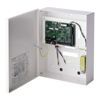
 Controller hardware
© Vanderbilt 2018 69 A6V10276959-d
11.2018

Table of Contents

Questions and Answers:

Question and Answer IconNeed help?

Do you have a question about the Vanderbilt SPC42 Series and is the answer not in the manual?

Vanderbilt SPC42 Series Specifications

General IconGeneral
BrandVanderbilt
ModelSPC42 Series
CategoryPower Supply
LanguageEnglish

Related product manuals