VEMCO – VR100 Manual 28 May 2018 60
Transmitter ID and Data
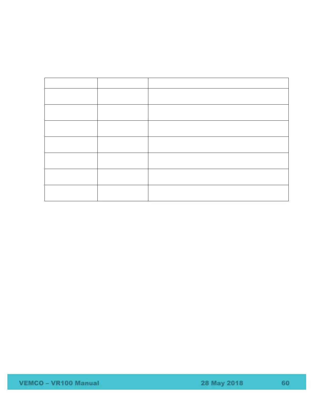
Transmitter data is displayed as shown in the table below. The sensor data received from a sensor
transmitter is displayed in the applicable units. The units shown on the Transmitter Type line are
configurable, as explained in section 2.1.3. Continuous sensor transmitters must be set up in the receiver
before they can be monitored (see section 2.2 or 3.8.1). Data received from a coded sensor transmitter
that has not been set up in the receiver will be displayed as raw data.
“P” indicates the detection is from a continuous pinger.
The period is given in milliseconds (ms).
“S1” indicates the data is from a one-sensor continuous
transmitter. The data is shown in the applicable units.
“S2” indicates the data is from a two-sensor continuous
transmitter. The data is shown in the applicable units.
“#” indicates that the coded pinger ID number follows.
Coded sensor
(with units)
The coded sensor ID number is given followed by the data
with applicable units.
Coded sensor
(without units)
The coded sensor ID number is given followed by the raw
sensor data.
Indicates a coded ping train was received that could not be
decoded.
Frequency / Code Space
For coded tags, the code space is displayed (see section 7.1.2 for an explanation of code space). For
continuous pinger and continuous sensor tags the frequency being monitored on this channel is shown in
kilohertz (kHz). Instructions on setting the channel frequency are given in section 2.3.
Last detection elapsed time
The length of time elapsed (in seconds) since the last detection (“LT” stands for “Last Time”). If the time
has been very long, the display will show 999 to indicate there haven’t been recent detections.