WARNING! In parallel UPS configuration, all operations related to disconnecting or connecting of the
maintenance bypass switch must be executed within three seconds to avoid overload situations and damage
to the maintenance bypass switch.
4. In the following order, close these switches output switch Q5, bypass input switch Q2, rectifier input switch Q1,
and all external output isolating switches (if any) of the UPS.
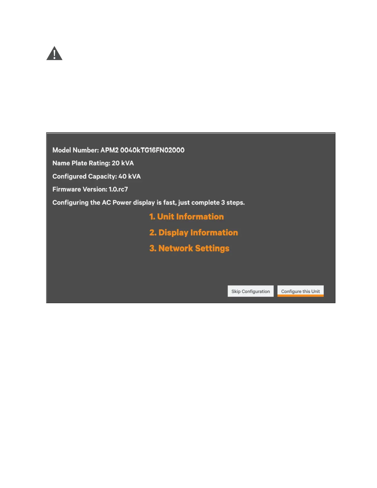
Now, the system is powered ON, and the startup screen pops up. As shown in Figure 6.2 below.
Figure 6.2 Startup Interface
Click Configure this unit, the system information will appear, as shown in Figure 6.3 on the next page.
6 Single UPS Operation Proprietary and Confidential ©2023 Vertiv Group Corp. 103
Vertiv™ Liebert® APM2 30 to 120 kVA Modular UPS User Manual