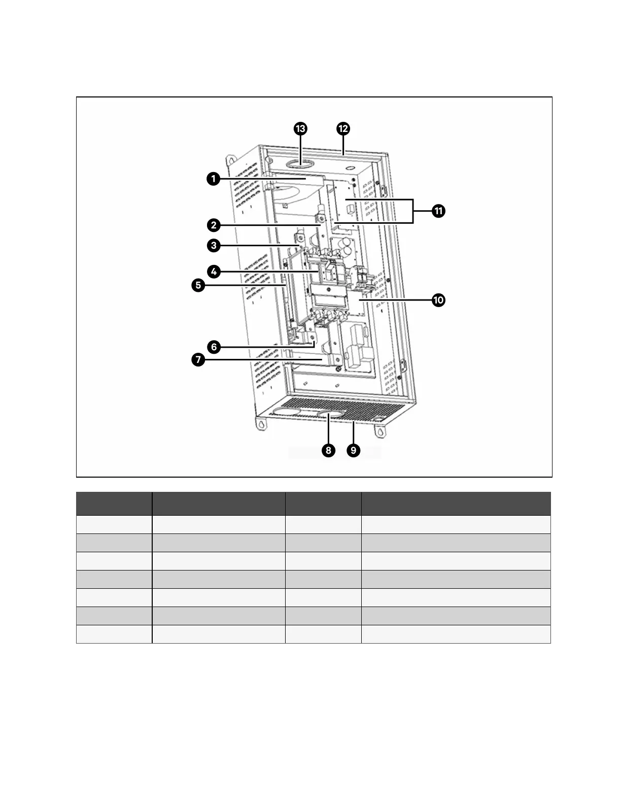
Figure 7.10 Internal Structure of BCB Box
Item Description Item Description
1 Battery ground fault detector 8 Bottom entry hole
2 Battery terminal (-) 9 Bottom plate
3 Battery terminal (+) 10 PCB board of battery ground fault detector
4 BCB 11 BCB Control board
5 PE 12 Top cover
6 UPS terminal (+) 13 Top entry hole
7 UPS terminal (-)
138 Proprietary and Confidential ©2023 Vertiv Group Corp. 7 Battery
Vertiv™ Liebert® APM2 30 to 120 kVA Modular UPS User Manual