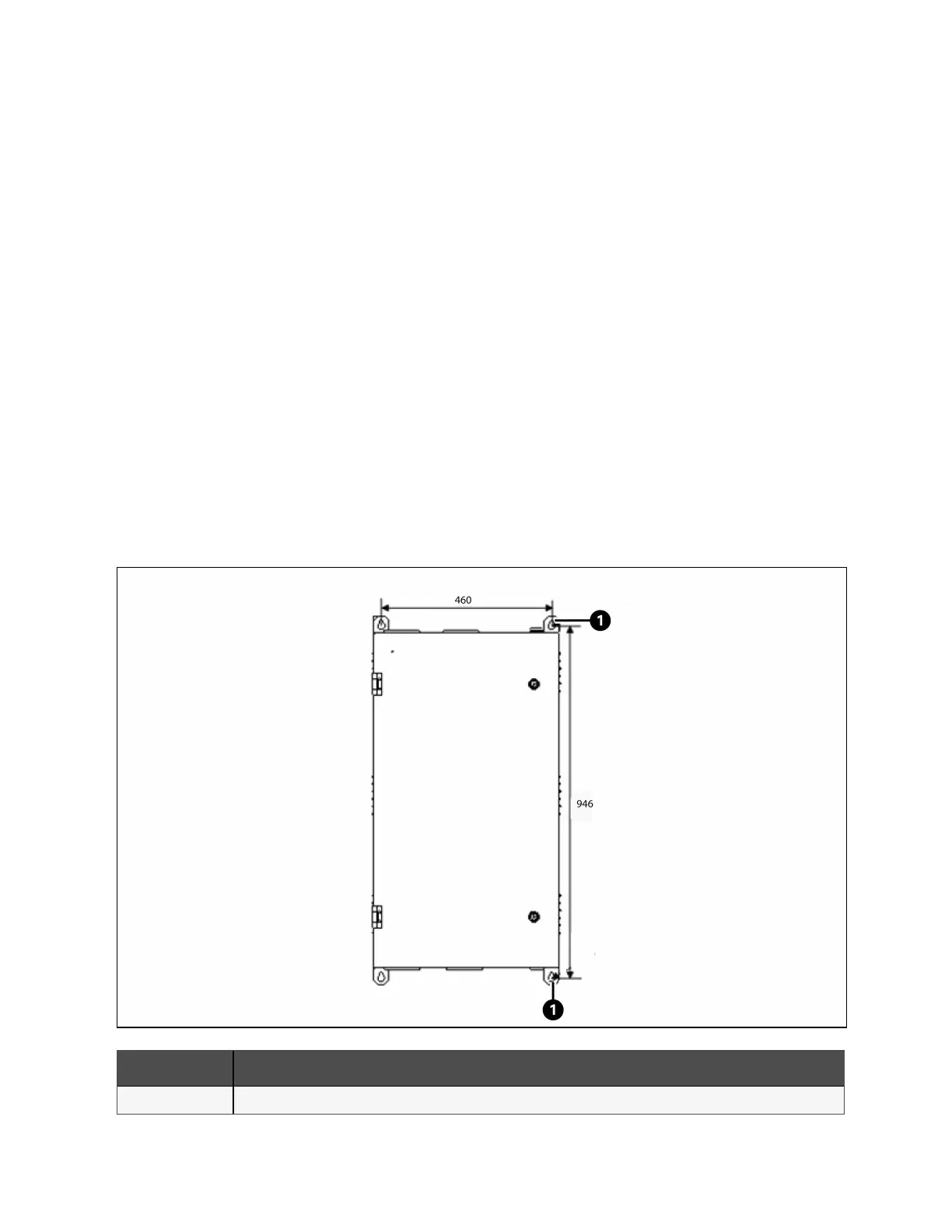
The BCB box should be installed close as possible to the battery. It can be installed on a wall or a horizontal surface through
the installation holes shown in Figure 7.9 below.
Refer to Figure 7.9 below to Figure 7.11 on page139 to install and connect the BCB box. There are connection terminals in the
BCB box for connecting the power cables from the UPS and battery. For signal cable connection, connect the accessory cable
W812 shown in Figure 7.11 on page139.
The BCB box can use top cable entry and bottom cable entry. It provides one big and one small cable entry holes on both the
top plate and bottom plate. The big one is for power cable entry, and the small one is for signal cable entry. After connection,
take appropriate measures to seal the cable entry holes.
NOTE: The signal cable must be connected separately from the battery power cables. The signal cable is a shield
cable, both ends of its shield layer must be connected to the enclosure. The UPS and BCB box must be earthed
separately.
NOTE: The battery switch box is recommended to be installed near the battery, and the working temperature is 0-40
°C.
NOTE: When using BCB, the user needs to manually modify the wiring sequence of the BCB dry contact terminal:
Connect to J3 of the X6 board, the order of terminals is black (thin, 2)-red (4)-orange (6)-brown (8)-black (thick, 16).
Connect to X7 board J1, the sort order is black (thin, 4)-red (6)-orange (8)-brown (10) or black (thin, 3)-red (5)-orange
(7)-brown ( 9). Connect to X7 board J2, and the sort order is black (thin, 4)-red (6)-orange (8)-brown (10).
Figure 7.9 Installation Hole Dimension of BCB Box (Units: mm)
Item Description
1 Installation hole
7 Battery Proprietary and Confidential ©2023 Vertiv Group Corp. 137
Vertiv™ Liebert® APM2 30 to 120 kVA Modular UPS User Manual