Maintenance mode
As shown in Figure 2.10 below, if the UPS maintenance or service is required, use the manual maintenance bypass switch to
transfer the load to maintenance bypass, with no interruption in power to the load. This maintenance bypass switch is fitted in
all UPS modules and rated for full load of a single module.
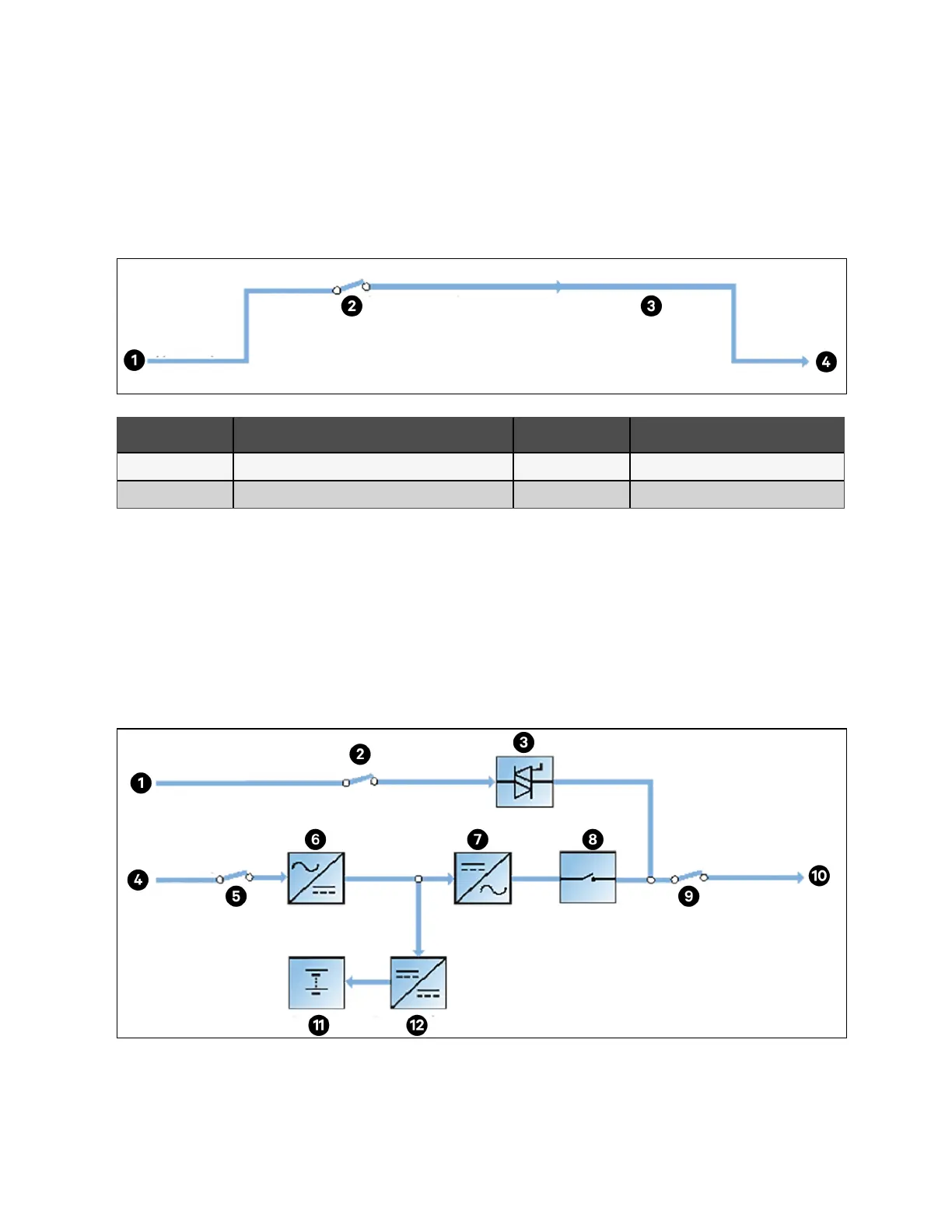
Figure 2.10 Schematic Diagram of Maintenance Mode
Item Description Item Description
1 Bypass input 3 Maintenance bypass
2 Maintenance bypass switch 4 UPS output
ECO mode
As shown in Figure 2.11 below, if ECO mode is selected, all power switches and the battery switches are closed except the
maintenance bypass switch, and the system puts the load on the bypass mode, for energy saving. When the bypass supply is
within the range of normal frequency and normal voltage (adjustable), the load is powered by the bypass, with the inverter on
standby. When the voltage and/or frequency of the bypass supply are beyond the pre-defined and adjustable limits, the
system will transfer to the inverter output. and the transfer time for switching from bypass to inverter is less than 2 ms
(uninterrupted) and less than 5 ms (interrupted). In this mode, the system can normally charge the battery.
Figure 2.11 Schematic Diagram of ECO Mode
2 Overview Proprietary and Confidential ©2023 Vertiv Group Corp. 17
Vertiv™ Liebert® APM2 30 to 120 kVA Modular UPS User Manual