18 020814.02
Installation manual BOW PRO Series Thrusters: BOWB285 - BOWB300 - BOWB320
DL
=
α
α : min. 0º
max. 15º
D = 300 mm (11
13
/
16
”)
L = 300 ... 900 mm (12 ...36”)
A
D
D = 300 mm
(11
13
/
16
”)
R = 30 mm
(1
3
/
16
”)
C = 30 ... 45 mm
(1
3
/
16
”
...
1
3
/
4
”)
R
R
B
C
C
D
R
R
C
A B C
D = 300 mm
(11
13
/
16
”)
R = 30 mm
(1
3
/
16
”)
C = 30 ... 45 mm
(1
3
/
16
”
...
1
3
/
4
”)
C
C
β
γ
γ
β
Sharp
C = 30...45 mm (
1
3
/
16
”...1
3
/
4
”
)
D = 300 mm (11
13
/
16
”)
β = β
γ = γ
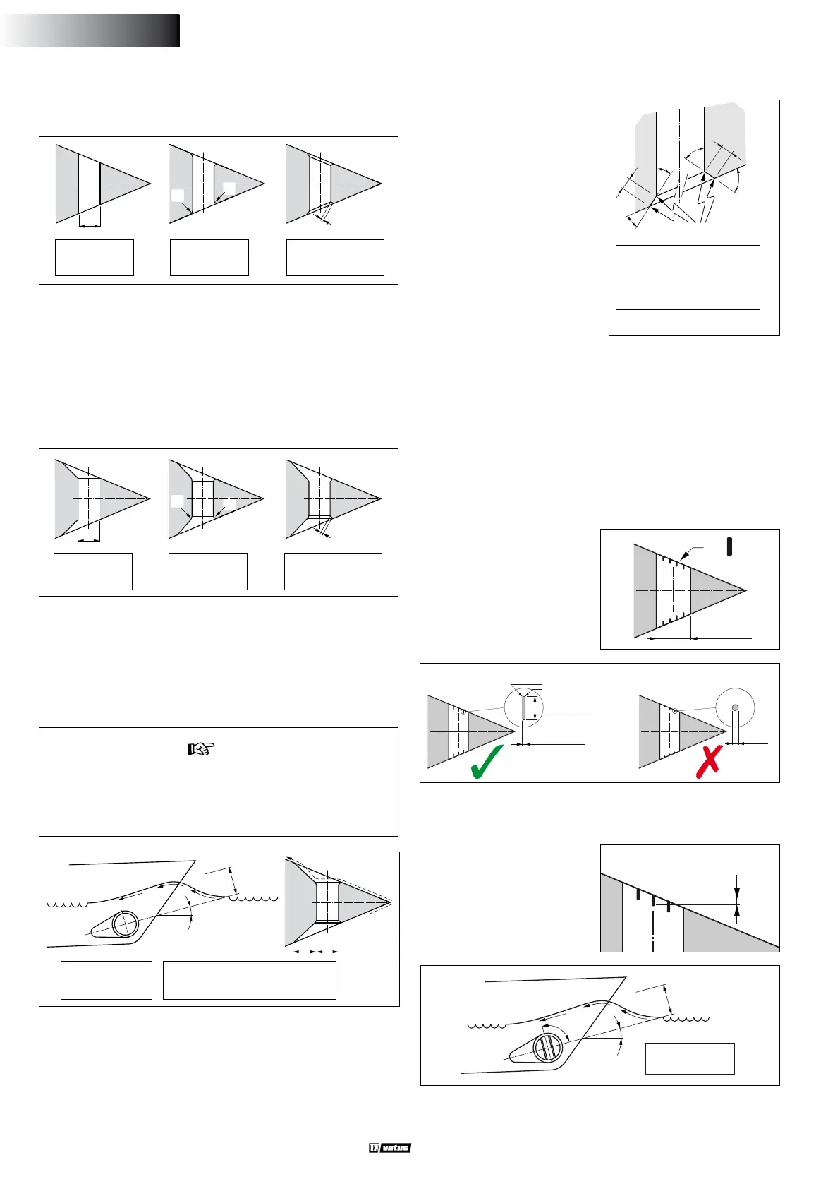
3.3 Connection of thrust tunnel to ship’s hull
tip:
The manner, in which the thrust tunnel is connected to the hull,
has a great inuence on the actual performance of the bow
thruster and to the drag the hull experiences when underway.
Direct connection of the tunnel to the hull, without a fairing, pro-
duces reasonable results.
A The connection to the hull can be abrupt.
B It is better to make the connection rounded with radius ‘R’ of
about 0.1 x D.
C It is even better to use sloping sides ‘C’ with dimensions 0.1 to
0.15 x D.
Connection of the thrust tunnel to the ship’s hull with a fairing results
in lower hull-resistance during normal sailing.
If the connection of the thrust
tunnel and the boat's hull is to
be made with a sloped side, it
should be executed in accord-
ance with the drawing.
Make the sloped side (C) with
a length of 0.1 to 0.15 x D and
make sure that the angle be-
tween the tunnel and the sloped
side will be identical to the angle
between the sloped side and the
ship’s hull.
A The connection with a fairing can be abrupt.
B It is better to make the connection with a fairing rounded with
radius ‘R’ of about 0.1 x D.
C The best connection is with a fairing using sloping side ‘C’ with
dimensions 0.1 to 0.15 x D.
- Length ‘L’ of the fairing should be between 1 x D and 3 x D.
- This fairing should be embodied in the ship’s hull in such a way
that the centreline of the fairing will correspond with the antici-
pated shape of the bow-wave.
3.4 Grid bars in the tunnel openings
Although the thrust force will be adversely aected, grid bars may be
placed into the tunnel openings, for protection of the thruster.
In order to limit the negative eect of this on the thrust and on hull
resistance during normal operation as much as possible, the follow-
ing must be taken into account:
4 x
300 mm
(11
13
/
16
”)
- The bars must have a rectangular cross-section.
- Do not t round bars.
- The bars must be installed so they are perpendicular to the ex-
pected waveform.
=
α
α : min. 0º
max. 15º
90º
Overlap
- Do not t more bars per
opening than is indicated in
the drawing.
- The bars must overlap a cer-
tain amount.
ø ...
3 mm (
1
/
8
”)
min. 20 mm (
3
/
4
”)
max. 40 mm (1
1
/
2
”)
ca. 0.7 x 0.7 mm
(
1
/
32
” x
1
/
32
”)
ENGLISH