75
Turbine Station Conguration Guide
A100K11194
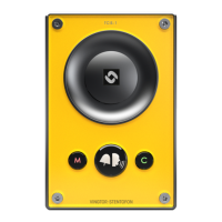
A.2 Input Connectors
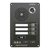
P3 10-pin plug-on terminal for external connections.
Pin 1 5.3V
Pin 2 GND
Pin 3 Button Input or LED Driver
Pin 4 Button Input or LED Driver
Pin 5 Button Input or LED Driver
Pin 6 Button Input or LED Driver
Pin 7 Button Input or LED Driver
Pin 8 Button Input or LED Driver
Pin 9 600 ohm balanced line out +
Pin 10 600 ohm balanced line out -
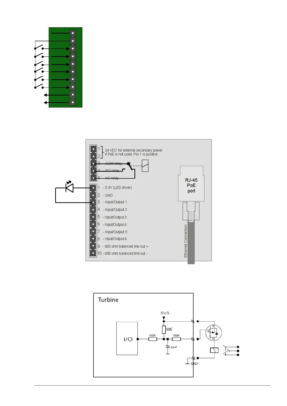
A.3 Output Connectors + 1 Relay
The extra relay for any of the 6 I/O pins is connected as shown:
5.3V
GND
1
6
10
I/O 1
I/O 2
I/O 3
I/O 4
I/O 5
I/O 6
GND
Line Out +
Line Out -
5
4
3
2
9
8
7
3
Outputs (1)
6 outputs + 1 relay
Door opening, call indication etc.
Turbine Station Web: Select usage as Output
AlphaPro – RCO Table: Map logical RCO to physical RCO
(Here: Logical RCO 39 is mapped to output 7 of station 139)
Turbine station - Output connectors
Output 7