Chapter 8 Deployment CPU 21xCAN Manual VIPA CPU 21x
8-10 HB103E - Rev. 05/45
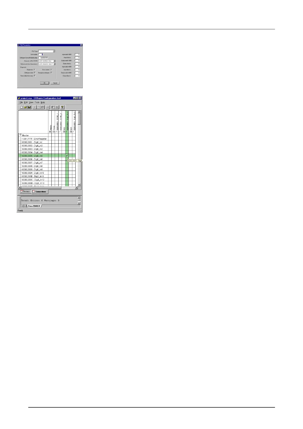
• Right click onto the master and open the VIPA specific dialog "Set PLC
Parameters". Here you may adjust the diagnosis behavior and the
address ranges that the master occupies in the CPU.
Under "Slot number" type the slot no. 0 for your CPU 21xCAN. At
export, WinCoCT creates the DB 2000.
• Change to the register "Connections" in the main window. Here the
process data are shown in a matrix as inputs (1
st
column) and as
outputs (1
st
row).
To monitor the process data of a device with a "+" click on the according
device.
• For helping you, you may only define a connection when the appearing
cross has green color. Select the according cell with the mouse pointer
in row and column in the matrix and click on it. → The cell is marked
with a "". You can control the connection by changing into "Devices",
click on the master and monitor the process image of the master via
"Device Access".
• Save your project.
• Via File > Export your CANopen project is exported into a wld-file. The
name is the combination of project name + node address + ID
Master/Slave.
Now your CANopen project engineering under WinCoCT is ready.
• Start the SIMATIC manager from Siemens with your PLC project for the
CPU 21xCAN.
• Open the wld-file via File > Memory Card File > open
• Copy the DB 2000 into your block directory.
As soon as you transfer this block to the CPU, it is recognized by the CPU
and the according parameters are transferred to the CAN master.
This is only possible if your CAN master CPU is included in the hardware
configuration as virtual Profibus system. The approach is to find at the
following pages.
Import into PLC
program

 Loading...


