30: Dynamic Multipoint Virtual Private Network (DMVPN)
_______________________________________________________________________________________________________
_____________________________________________________________________________________________________
© Virtual Access 2017
GW1000 Series User Manual
Issue: 1.9 Page 282 of 350
30.3 DMVPN scenarios
30.3.1 Scenario 1
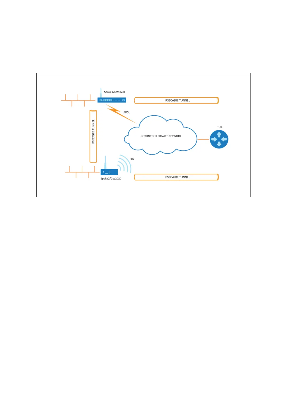
Spoke1, spoke2 and a hub are in the same public or private network.
Figure 141: Network diagram for DMVPN spoke to spoke
Spoke1 and spoke2 connect on their WAN interface: ADSL, 3G and initiate main
mode IPSec in transport mode to the hub.
After an IPSec tunnel is established, spokes register their NHRP membership with
the hub.
GRE tunnels come up.
Hub caches the GRE tunnel and real IP addresses of each spoke.
When spoke1 wants to talk to spoke2, it sends an NHRP resolution request to the
hub.
The hub checks its cache table and forwards that request to spoke2.
Spoke2 caches spoke1’s GRE and real IP address and sends an NHRP resolution
reply via the hub.
Spoke1 receives an NHRP resolution reply and updates its NHRP table with
spoke2 information. Then it initiates VPN IPSec connection to spoke2.
When an IPSec tunnel is established, spoke1 and spoke2 can send traffic directly
to each other.
 Loading...