Cables and cable harnesses,
all engines
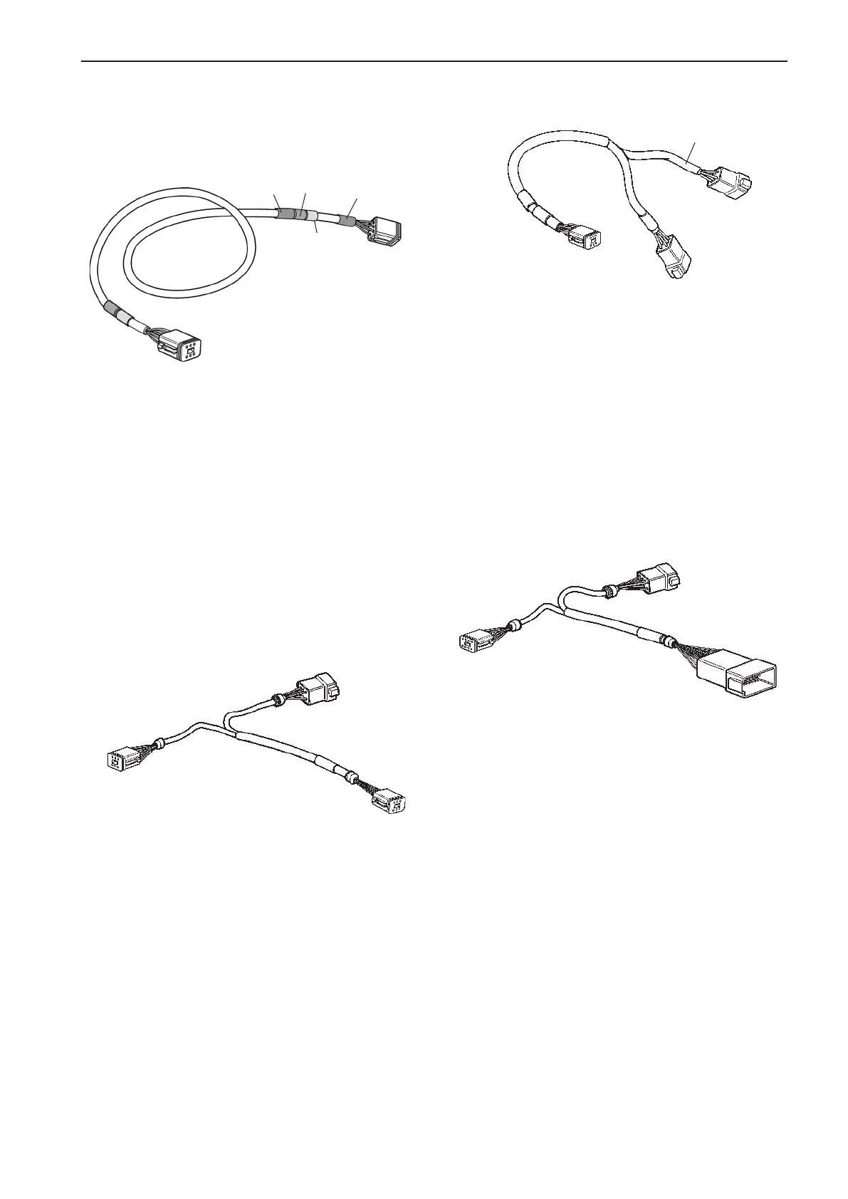
Standard bus cable, 6-pin
The cable must be used to connect the PCU to the
HCU.
NOTE! The cable has female connections in both
ends and cannot be used as an extension.
Two female connectors.
Length m: 5, 7, 9, 11, 13
Length ft: 16, 23, 30, 36, 42
Y-connector, EVC bus cable, 6-pin
Y-split multilink, 6-pin
For making branches in the multilink cabling, EVC
display–sync. connection–NMEA-connection.
NOTE! Do not install an Y-split cable without having
the MULTILINK BREAKOUT connected.
Length, m (ft): 0.5 (1.6)
Y-connector to 4–20 mA output interface,
engine transmission cable, 8 and 12-pin
Part No.
0.25 m (0.8 ft)
0.25 m (0.8 ft)
0.5 m (1.6 ft)
To connect the standard bus cable to the HCU in sys-
tems with secondary helm stations.
Length, m: 0.25 x 0.25 x 0.5
Length, ft: 0.8 x 0.8 x 1.6
MULTILINK
Yellow label
Part No.
Yellow PVC-coating
MULTILINK BREAKOUT
MULTILINK
Yellow label
To connect the 4–20 mA interface output to an af-
termarket control system supporting 4–20 mA, i.e. a
CP-control (pitch) system.
The cable is connected to the EMS unit cable
(ENGINE CONN) on the engine/transmission cable
harness.
This connector is not used on D4 and D6 engines
with sterndrive DPH and DPR.
Length, m: 0.2 x 2.0
Length, ft: 0.7 x 6
Part No.
Red
Green
Red
Green
CONN X2
Green
8-pin con-
nection
8-pin con-
nection
12-pin con-
nection
0.15 m (0.5 ft)
0.15 m (0.5 ft)
0.20 m (0.7 ft)
25
EVC-C Major components



 To Next Page