CFW700 | 21
Installation and Connection
English
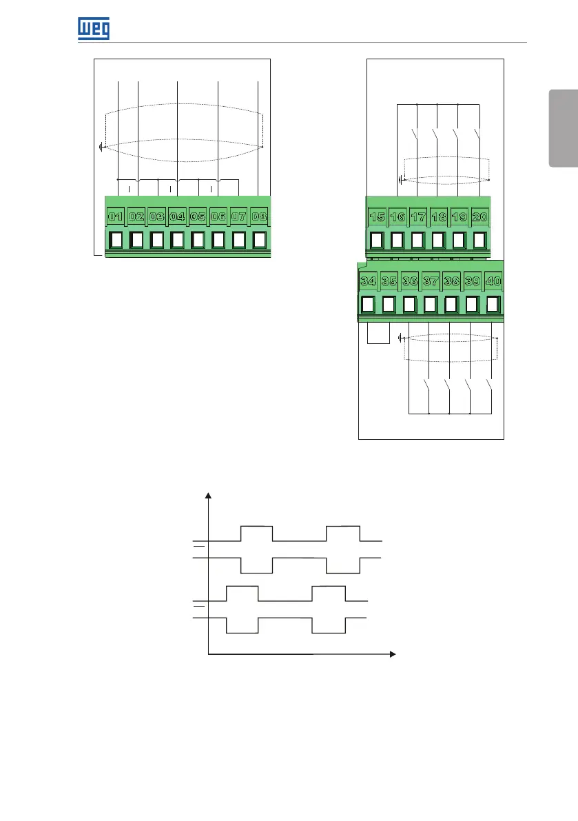
+24 V
GND (24 V)
DI5
DI6
DI7
DI8
Active low digital inputs
+24 V
COM
GND (24 V)
DI1
DI2
DI3
DI4
(c) Active low digital inputs
Open collector encoder
Z
Z
Z
B
B
B
A
A A
+V(5 V)
+5 V-ENC
GND-ENC COM
(b) Encoder with open collector
output
Figure 3.5: (a) to (c) XC1 connection terminals
Signal
Time
A
B
A
B
Figure 3.6: Sequence of the encoder signals
Refer to Figure A.3 on page 202 to find the control board, the XC1 connector (control
signals), the S1 DIP-switches (to select the type of signal of the analog inputs and outputs)
and S2 (RS-485 network termination) and slots 3 and 5 for accessories (see section 7.2
ACCESSORIES on page 58).
The CFW700 inverters are supplied with the digital inputs configured as active high and the