CFW700 | 23
Installation and Connection
English
Table 3.2: Technical specifications for the encoder and the encoder cable
Characteristics Specifications
Encoder
Power supply 5 V
Channels
2 channels in quadrature (90º) + zero pulses with complementary outputs
(differentials) or open-collector.
Signals
A, A, B, B, Z and Z
Available for 2 channels: A,
A
, B,
B
.
If the channel zis not used, leave the terminals XC1: 6 and 7 not
connected. Noother setting are necessary.
Output circuit Linedrive type, push-pull or open-collector. Maximum voltage of 12 V.
Isolation Electronic circuit isolated from the encoder frame.
Pulses Recommended number of pulses per rotation = 1024 ppr.
Frequency Maximum allowed = 100 kHz.
Encoder
cable
Type of cable Balanced cable shield (for differential signals operation).
Connection
The cable shield must be connected to ground through devices on
control shield plate (see Figure 3.5 on page 21).
Distance ≥ 25 cm of other wiring.
Isolation Use metal conduit.
Length Maximum = 10 m.
Follow instructions below for the proper installation of the control wiring:
1. Wire gauge: 0.5 mm² (20 AWG) to 1.5 mm² (14 AWG).
2. Maximum tightening torque: 0.50 N.m (4.50 lbf.in).
3. Use shielded cables for the connections in XC1 and run the cables separated from the
remaining circuits (power, 110 V / 220 Vac control, etc.), according to item 3.2.6 Cable
Distances on page 23. If control wiring must cross other cables (power cables for instance),
make it cross perpendicular to the wiring and provide a minimum separation of 5 cm (1.9 in)
at the crossing point.
Refer to item 3.2.6 Cable Distances on page 23, for the proper cable distances.
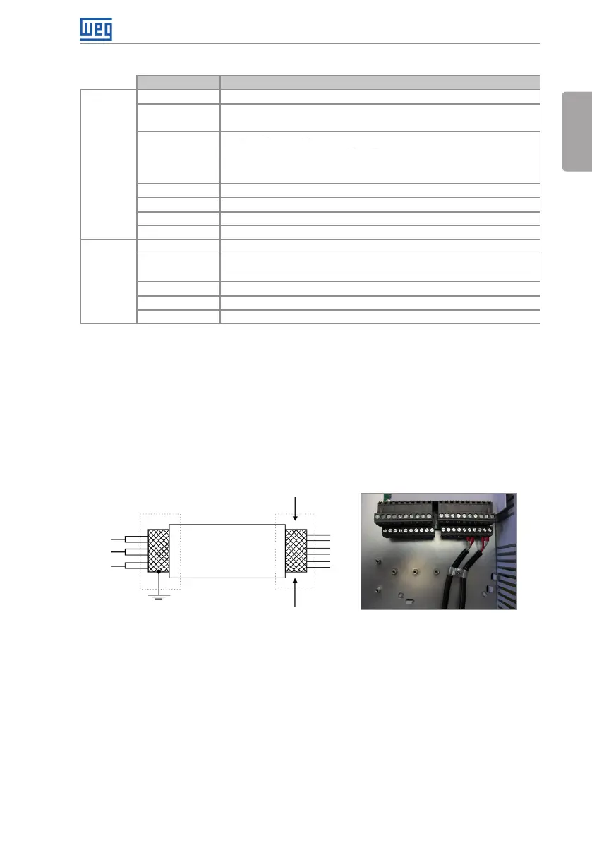
Do not ground
Inverter
side
Isolate with tape
(a) Cable shield connection
(b) Connection sample of the shield to
ground
Figure 3.7: (a) and (b) Shield connection
4. Relays, contactors, solenoids or coils of electromechanical brakes installed close to the
inverter may eventually create interferences in the control circuitry. To eliminate this effect,
RC suppressors (with AC power supply) or free-wheel diodes (with DC power supply) shall
be connected in parallel to the coils of these devices.
3.2.6 Cable Distances
The power cables and control cables must be separated (relay output cables and other control
cables) according to Table 3.3 on page 24.