12 | CFW700
Installation and Connection
English
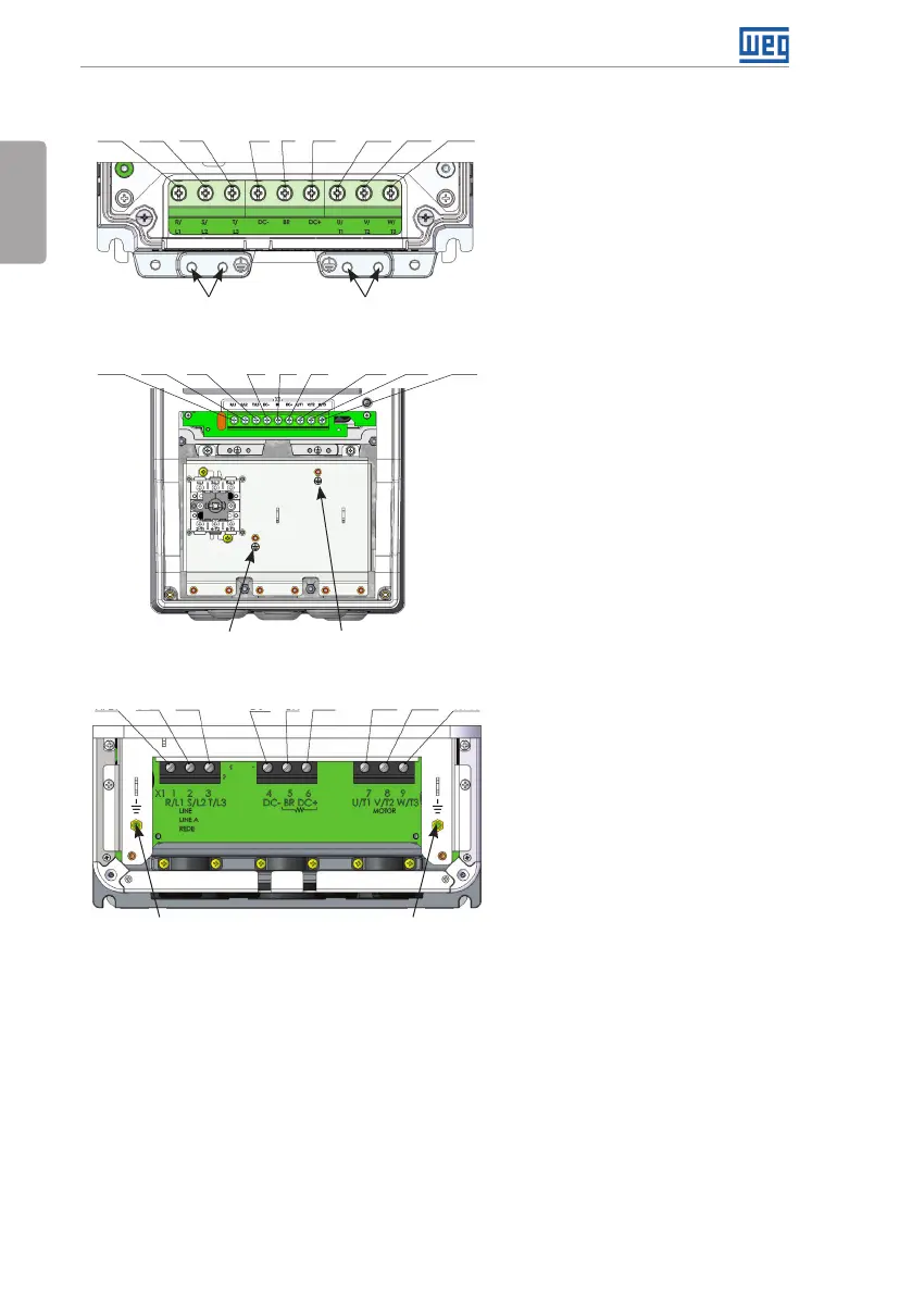
3.2.1 Identification of the Power and Grounding Terminals
Ground
Ground
R/L1
R/L1
S/L2
S/L2
T/L3
T/L3
DC-
DC-
DC+
DC+
U/T1
U/T1
V/T2
V/T2
W/T3
W/T3
BR
BR
(a) Frame sizes A, B and C
(b) Frame sizes B and C with degree of protection IP55
Ground Ground
(c) Frame size D
R/L1 S/L2 T/L3 DC- DC+ U/T1 V/T2 W/T3
BR
Ground
Ground
R/L1, S/L2, T/L3: AC power supply.
DC-: this is the negative potential
terminal in the DC bus circuit.
BR: braking resistor connection.
DC+: this is the positive potential
terminal in the DC bus circuit.
U/T1, V/T2, W/T3: motor connection.