14 | CFW700
Installation and Connection
English
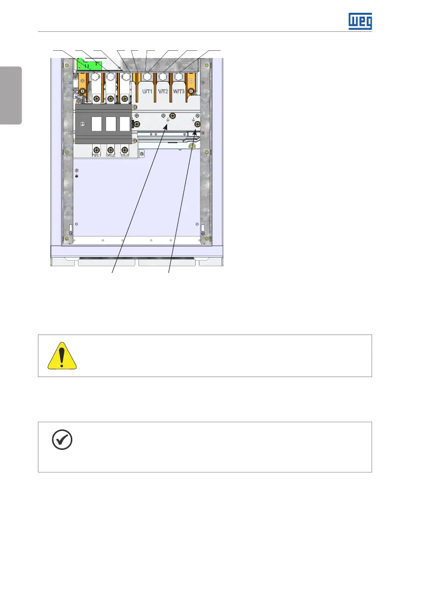
R/L1 S/L2 T/L3 DC- DC+ U/T1 V/T2 W/T3BR
Ground
Ground
(f) Frame size E with degree of protection IP55
Figure 3.1: (a) to (f) Power terminals and grounding points - frame sizes A to E
3.2.2 Power / Grounding Wiring and Fuses
ATTENTION!
Use proper cable lugs for the power and grounding connection cables.
Refer to Table B.1 on page 212, Table B.2 on page 213 and Table B.3 on page 214 for the
recommended wiring and fuses and Table B.5 on page 223 for the specifications of the power
terminals.
NOTE!
The gauges values presented in Table B.1 on page 212, Table B.2 on page 213
and Table B.3 on page 214 are for reference only. Installation conditions and the
maximum permitted voltage drop shall be considered for the proper wiring sizing.
Input fuses
The fuses to be used at the input must be HS (High-Speed) type with I
2
t equal or lower the
value indicated in the Table B.1 on page 212, Table B.2 on page 213 and Table B.3 on
page 214 (consider extinction current value in cold situation (it is not the fusion value)), to
protect the inverter diode rectifiers and input wiring.
In order to meet UL requirements, use class J fuses at the inverter supply with a current not
higher than the values presented in Table B.1 on page 212, Table B.2 on page 213 and
Table B.3 on page 214.