CHAPTER 7 - PROGRAMMING INFORMATION AND SUGGESTIONS
150
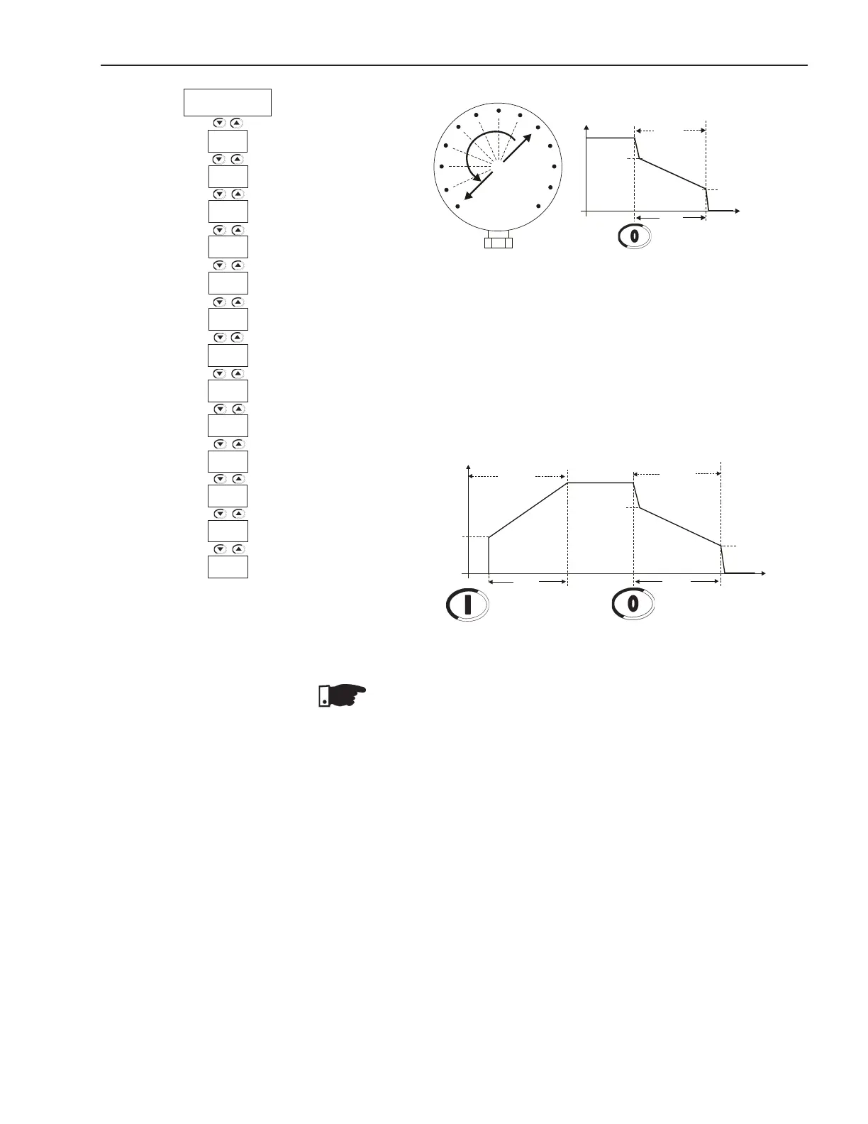
Figure 7.9 - Manometer showing the pressure drop
9) Generally, the current increases at the end of the deceleration
ramp and in this case the motor requires more torque to achieve
asmoothwaterowstop.Whenthemotorhasalreadystopped,
but is still enabled, the current will increase too much. To prevent
this condition, set P105 to a value that as soon it stop it is also
disabled;
10) Set P610 and P611 to current and time levels that prevent the
hydraulic pump from running without a load.
NOTES!
1) P400 and P401 must be set according to the line voltage and the
nominal current of the used motor;
2) Ifthehydraulicpipingisnotttedwithamanometer,thewater
hammer can be noted at the pressure relief valves;
3) Please consider, that sudden line voltage drops results in motor
torque drops. Thus, ensure that the power supply line characte-
ristics are within the characteristics required for motor operation;
4) If errors are detected during the motor start, check all connections
of the Soft-Starter to the power line, the motor connections, the
voltage levels of the power line, the fuses, circuit-breakers and
disconnecting switches.
Figure 7.10 - Start with pump control
U(V)
Start
Stop
P101
P102
0
Enable
Disable
t(s)
100%Un
Pump Control
P103
P104
P105
Disable
P104
t(s)
0
P103
U(V)
Stop
100%Un
P105
P611
P610
P401
P400
Pump
Control
P105
P104
P103
P102
P101
P130
P640
P406
P620