Troubleshooting Guide
Power Feed Circuit Troubleshooting
Troubleshooting Guide 60HDdoc102619 6-8
6
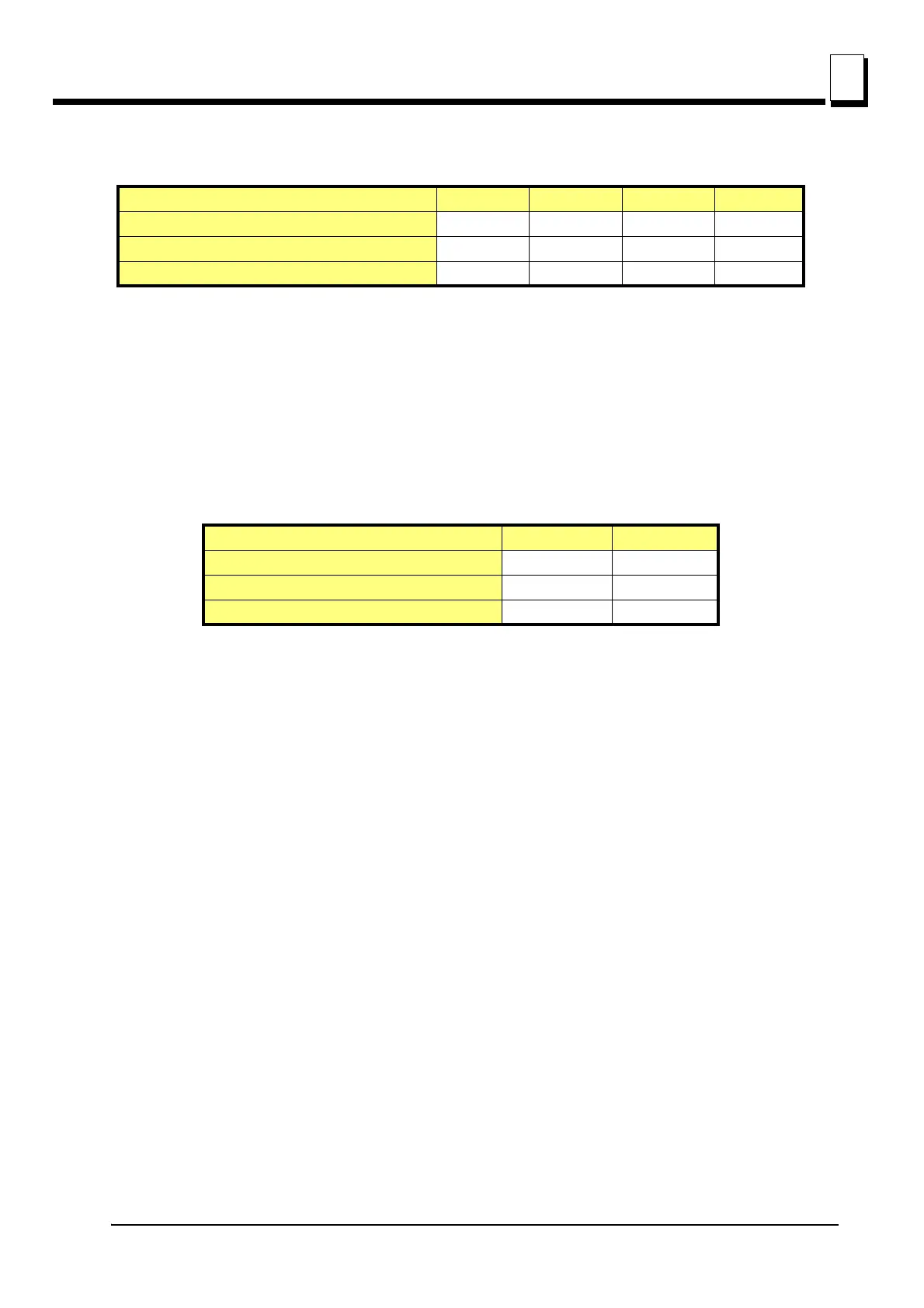
See Table 6-1. The drum switch positions and light states with the feed rate dial switch all the way
up are shown below.
Please contact Customer Service for assistance if necessary when troubleshooting the system using
these lights.
S1, S2 - These two red lights indicate the position of the power feed drum switch. Three possible
positions are shown in table below. If the lights are not on or off as shown, the power feed drum
switch is probably miswired or defective.
See Table 6-2. The light states and drum switch positions are shown below.
OUT1 - This red light is on when power is applied to the accessory solenoid. When the OUT1 is off,
the accessory solenoid is not powered. Check the jumper cable connecting Vkey1 and Vkey2 Termi-
nals. Reconnect if necessary. If the light is still off the accessory solenoid may be defective.
Vcc - The Vcc light is on when power is applied to the Vkey2 Terminal. If the light is off, check all con-
nections to the key switch. Also check the fuse located between the Vkey2 terminal and the key
switch. Check the 225 Amp fuse in the fuse box. Make sure the battery connections are correct.
Vcc2 - This red light indicates that power is applied at the control circuits from the key switch. The
light is off when the Vcc light is off. Refer to the Vcc light problems when troubleshooting this light.
Vcc3 - This red light is on indicating the power feed control circuits. The light is off when the Vcc and
Vcc2 are off. Refer to the Vcc light to solve potential problems.
Power Feed Drum Switch Position BL TL BR TR
FORWARD On Off Off On
REVERSE Off On On Off
NEUTRAL On Off On Off
TABLE 6-1
Power Feed Drum Switch Position S1 S2
FORWARD On Off
REVERSE Off On
NEUTRAL On On
TABLE 6-2
 Loading...