Sawmill Alignment
Complete Alignment Procedure
7
7-36 60HDdoc102619 Sawmill Alignment
screw and tighten the bottom screw. Tighten the jam nuts and recheck the tilt of the blade.
6. Move the blade guide alignment tool close to the inner blade guide roller assembly and repeat the
above steps. Adjust the vertical tilt of the inner blade guide if necessary.
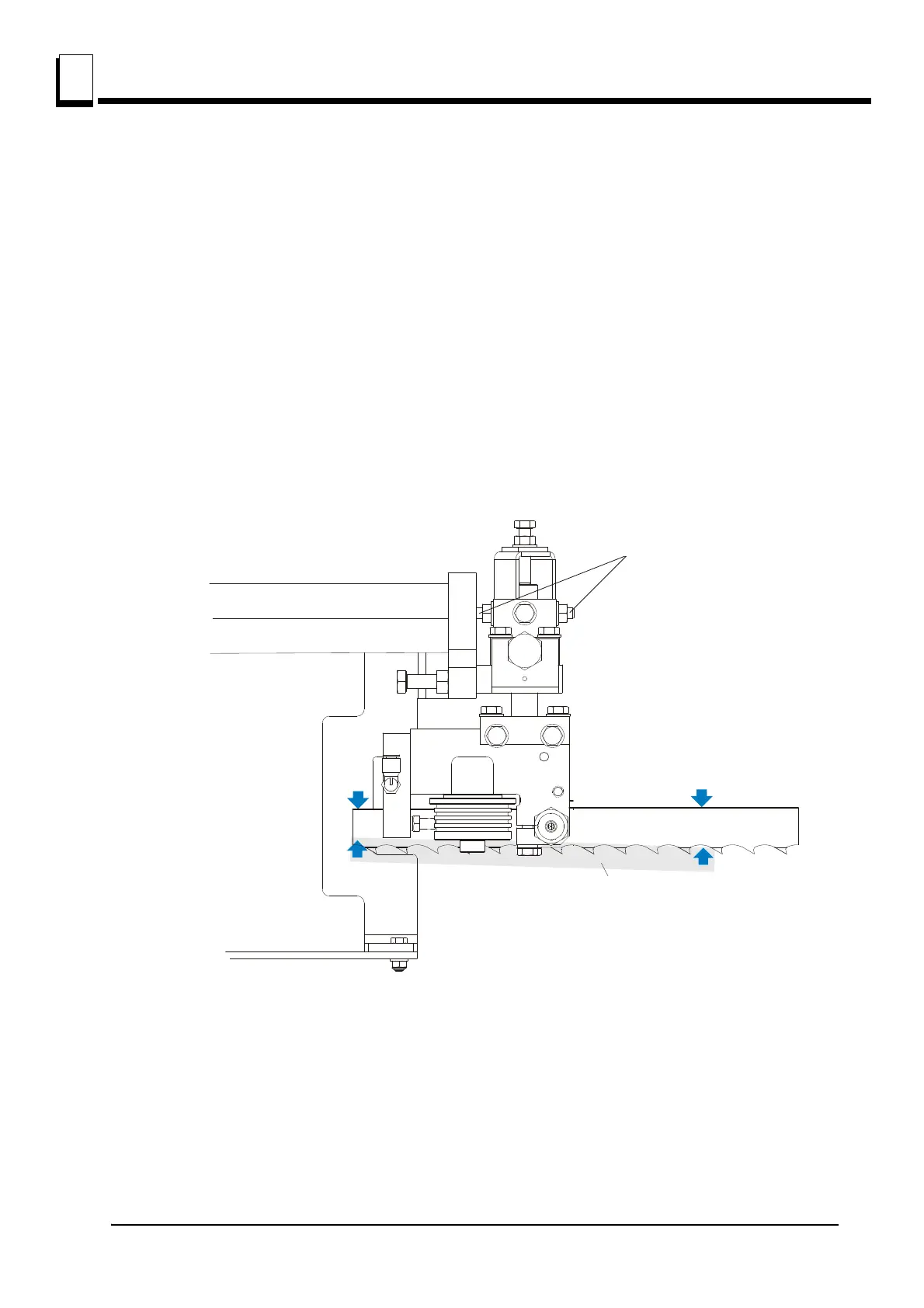
Blade Guide Horizontal Tilt Adjustment
If the blade guides are tilted in the wrong direction horizontally, the back of the blade may contact the
flange as the roller is spinning down, causing it to push the blade away from the guide roller.
1. Remove the blade guide alignment tool from the blade and adjust the blade guide arm halfway in.
2. Remove the clip from the blade guide alignment tool. Place the tool against the face of the outer
blade guide roller.
See Figure 7-37.
3. Measure between the back edge of the blade and the tool at the end closest to the inner blade guide
("B").
4. Measure between the back edge of the blade and the other end of the tool ("A").
The roller should be tilted slightly to the left (’A’ 1/8" [3 mm] less than ’B’ ±1/8" [3 mm]).
See Figure 7-38. Loosen the jam nuts on the horizontal tilt adjustment screws. To tilt the roller left,
FIG. 7-37
Horizontal Tilt
Adjustment Screws
A
Horizontal Tilt
Adjustment Screws
Blade Guide
Alignment Tool
 Loading...