Sawmill Alignment
Complete Alignment Procedure
Sawmill Alignment 60HDdoc102619 7-27
7
Blade Guide Installation
Each Wood-Mizer sawmill has two blade guide assemblies that help the blade maintain a straight
cut. The two blade guide assemblies are positioned on the saw head to guide the blade on each side
of the material being cut.
One blade guide assembly is mounted in a stationary position on the drive side of the saw head. This
assembly is referred to as the "inner" blade guide assembly.
The other blade guide assembly is mounted on the idle side of the saw head. It is referred to as the
"outer" assembly and is adjustable for various widths of materials to be processed.
NOTE: Before installing the blade guide assemblies, remove the blade
guide adjusting screws and apply a lubricating oil such as 10W30 or
Dexron III to each screw. This will prevent the screws and threaded
holes from corroding and make screw adjustments easier.
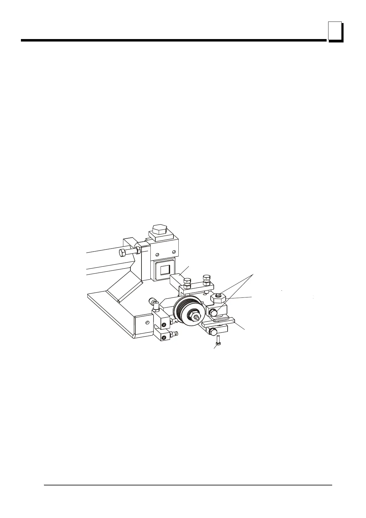
1. Inspect the guide disks and repair or replace as necessary. Remove the blade from the sawmill.
2. Loosen the top disk clamp bolt and mounting bolt. Turn the adjustment bolt counterclockwise to raise
the top disk all the way up. Remove the bottom guide disk from each blade guide assembly and
install the provided alignment bar.
3. Install each blade guide assembly to the mounting blocks and push all the way back. Install, tension
and track a new blade. Adjust the outer blade guide assembly so the roller flange is 3mm from the
back of the blade. Adjust the inner blade guide assembly so the roller flange is 3mm from the blade.
See Figure 7-28.
FIG. 7-27
bar
600122-3
Loosen top disk
mounting bolt
and clamp bolt
into mounting block
Turn adjustment bolt
counterclockwise to
raise top disk all the
way up
Insert guide assembly
into mounting block
Loosen top disk
mounting bolt
and clamp bolt
Turn adjustment bolt
counterclockwise to
raise top disk all the
way up
Remove bottom disk
and install alignment
bar
M5x10 Socket
Head Bolt
 Loading...