Protective Elements
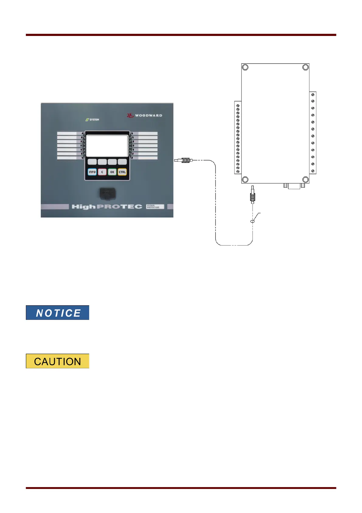
URTDII Module Fiber Optic Connection to the Protective Device
The figure above shows the fiber optic connections between the URTDII Module and the protective device. The
protective device supports the optical fiber connection.
Preassembled plastic optical fibers with connectors can be ordered from any distributor of optical fiber products. In
addition, these same distributors offer long rolls of cable with connectors that can be installed in the field. Some
distributors will make custom lengths to order.
Surplus length of a pre-cut fiber does not cause a problems. Simply coil
and tie the excess fiber at a convenient point. Avoid high tie pressure.
Bending radius of the fiber should be greater than 2 in. (50.8 mm).
The fiber termination at the URTDII simply snaps into or out of the connector. To connect the fiber termination at
the protective device, push the plug of the fiber optic onto the device interface then turn it until it “snaps”.
The protective device as well as the URTDII have various power supply
options. Make certain that the power supply is acceptable for both units before
connecting the same power supply to both devices.
1107 MCDGV4 DOK-HB-MCDGV4-2E