Protective Elements
Consult the URTDII Module Instruction Leaflet for complete instructions.
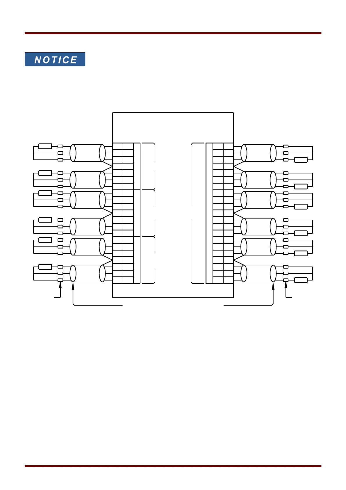
Three URTD terminals are provided for each RTD input.
The three terminals for any unused RTD input channel should be wired together. For example, if MW5 and MW6
are unused, MW5 terminals J2-15, J2-16, and J2-17 should be wired together and MW6 terminals J2-19, J2-20, J2-
21 should be separately wired together.
See the figure above for wiring of RTDs to the URTD inputs. Use three-conductor shielded cable. Note the
connection rules in the figure. When making connections to a two-lead RTD, connect two of the cable conductors
to one of the RTD leads as shown. Make this connection as close to the protected object as possible. Connect the
third cable conductor to the remaining RTD lead.
Connect the shield / drain wire to the Shield terminal as shown in the figure. The RTD cable shield should be
connected only at the URTD end, and insulated at the RTD end. The RTD's themselves must not be grounded at
the object to be protected.
Remember to set the URTDII module DIP switches according to the types of RTDs in each of the channels.
1108 MCDGV4 DOK-HB-MCDGV4-2E