Input, Output and LED Settings
DI-8P X
DI Slot X1
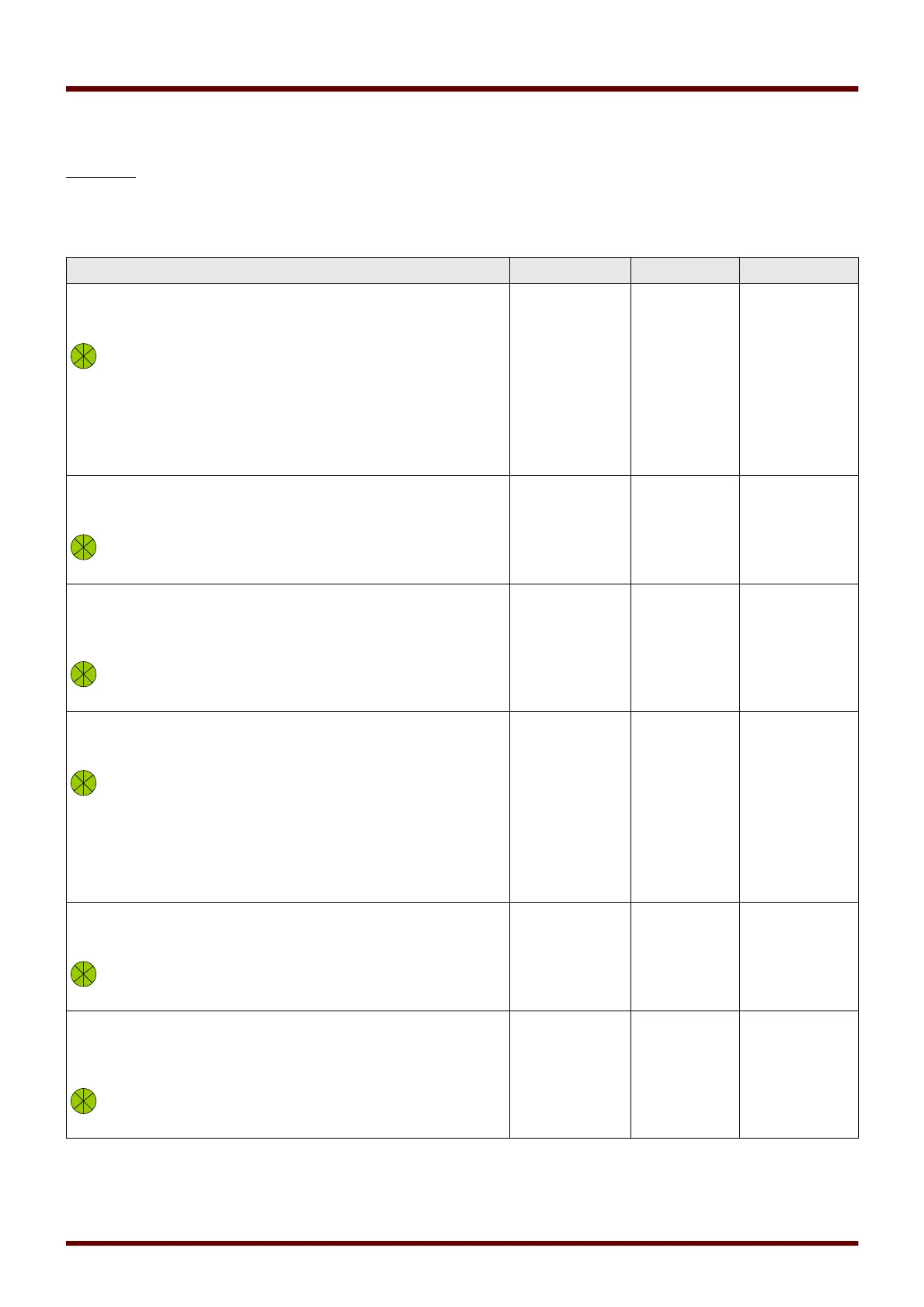
Device Parameters of the Digital Inputs on DI-8P X
Parameter Description Setting range Default Menu path
Nom voltage Nominal voltage of the digital inputs 24 V DC,
48 V DC,
60 V DC,
110 V DC,
230 V DC,
110 V AC,
230 V AC
24 V DC [Device Para
/Digital Inputs
/DI Slot X1
/Group 1]
Inverting 1 Inverting the input signals. inactive,
active
inactive [Device Para
/Digital Inputs
/DI Slot X1
/Group 1]
Debouncing
time 1
A change of the state of a digital input will
only be recognized after the debouncing
time has expired (become effective). Thus,
transient signals will not be misinterpreted.
no debouncing
time,
20 ms,
50 ms,
100 ms
no
debouncing
time
[Device Para
/Digital Inputs
/DI Slot X1
/Group 1]
Nom voltage Nominal voltage of the digital inputs 24 V DC,
48 V DC,
60 V DC,
110 V DC,
230 V DC,
110 V AC,
230 V AC
24 V DC [Device Para
/Digital Inputs
/DI Slot X1
/Group 2]
Inverting 2 Inverting the input signals. inactive,
active
inactive [Device Para
/Digital Inputs
/DI Slot X1
/Group 2]
Debouncing
time 2
A change of the state of a digital input will
only be recognized after the debouncing
time has expired (become effective). Thus,
transient signals will not be misinterpreted.
no debouncing
time,
20 ms,
50 ms,
100 ms
no
debouncing
time
[Device Para
/Digital Inputs
/DI Slot X1
/Group 2]
111 MCDGV4 DOK-HB-MCDGV4-2E