Installation and Connection
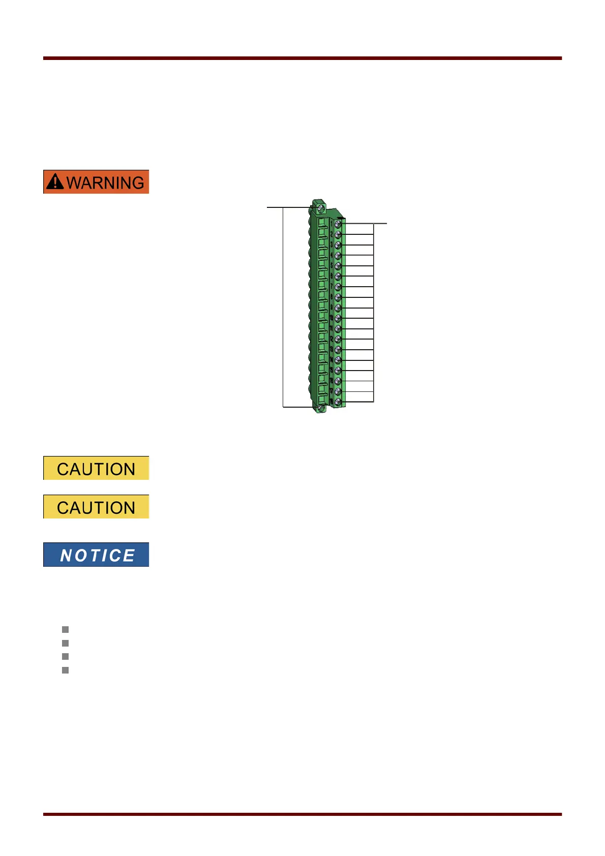
DI8 X – Digital Inputs
This module is provided with 8 grouped digital inputs.
In chapter [Device parameter/Digital Inputs] the assignment of the digital inputs is specified.
Ensure the correct tightening torques.
When using DC supply, the negative potential has to be connected to the
common terminal (COM1, COM2, COM3 - please see the terminal marking).
For each digital input group the related voltage input range has to be
parameterized. Wrong switching thresholds can result in
malfunctions/wrong signal transfer times.
Via the »assignment list« the states of the digital inputs are assigned to the
module inputs (e.g. I[1]).
The digital inputs are provided with different switching thresholds (can be parameterized) (two AC and five DC input
ranges). For each group the following switching thresholds can be defined:
24V DC
48V DC / 60V DC
110 V AC/DC
230 V AC/DC
If a voltage >80% of the set switching threshold is applied at the digital input, the state change is recognized
(physically “1”). If the voltage is below 40% of the set switching threshold, the device detects physically “0”.
60 MCDGV4 DOK-HB-MCDGV4-2E