Protective Elements
Parameter Description Setting range Default Menu path
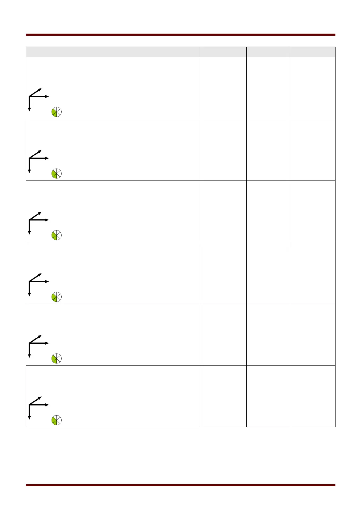
Polyg.Pos.Imp.R
.Ang.1
Polygon characteristic: The »Positive
Impedance Reach Angle 1« is the tilt angle
of the line element which is starting at the
positive impedance reach tip and spreads
on the right side in the first quadrant.
-30 - 5° 0° [Protection
Para
/<1..4>
/Z
/Z[1]
/Characteristic]
Polyg.Pos.Imp.R
.Ang.2
Polygon characteristic: The »Positive
Impedance Reach Angle 2« is the tilt angle
of the line element which is starting at the
positive impedance reach tip and spreads
leftwards, to the second quadrant.
175 - 210° 180° [Protection
Para
/<1..4>
/Z
/Z[1]
/Characteristic]
Polyg.Pos.Resis.
Reach
Polygon characteristic: The »Positive
Resistive Reach« determines the reach on
the positive R-axis (secondary value) and is
used to limit the coverage for fault
resistance and encroachment of the load
impedance into the characteristics.
0.2 - 500.0Ω 8.0Ω [Protection
Para
/<1..4>
/Z
/Z[1]
/Characteristic]
Polyg.Pos.Resis.
Ang.1
Polygon characteristic: The »Positive
Resistive Angle 1« is a tilt angle in the first
quadrant. The area right from the blinder is
excluded from the operating area.
50 - 90° 60° [Protection
Para
/<1..4>
/Z
/Z[1]
/Characteristic]
Polyg.Pos.Resis.
Ang.2
Polygon characteristic: The »Positive
Resistive Angle 2« is a tilt angle in the
fourth quadrant.
225 - 270° 240° [Protection
Para
/<1..4>
/Z
/Z[1]
/Characteristic]
Polyg.Neg.Imp.
Reach
Polygon characteristic: The »Negative
Impedance Reach« is the amplitude of the
negative impedance phasor (secondary
value) in the reverse (backward) direction
(3rd quadrant).
0.2 - 500.0Ω 2Ω [Protection
Para
/<1..4>
/Z
/Z[1]
/Characteristic]
840 MCDGV4 DOK-HB-MCDGV4-2E