January 2016
4-30
WorkCentre WorkCentre 4150/4250/4260WorkCentre 4150/4250/42604150/
REP 4.3
Repairs and Adjustments
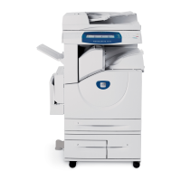
6. Remove the clutches (Figure 2).
Figure 2 Removing the Clutches
7. Release all harnesses from the cable clamps on the Main Drive Assembly. Route the har-
nesses away from the Main Drive Assembly.
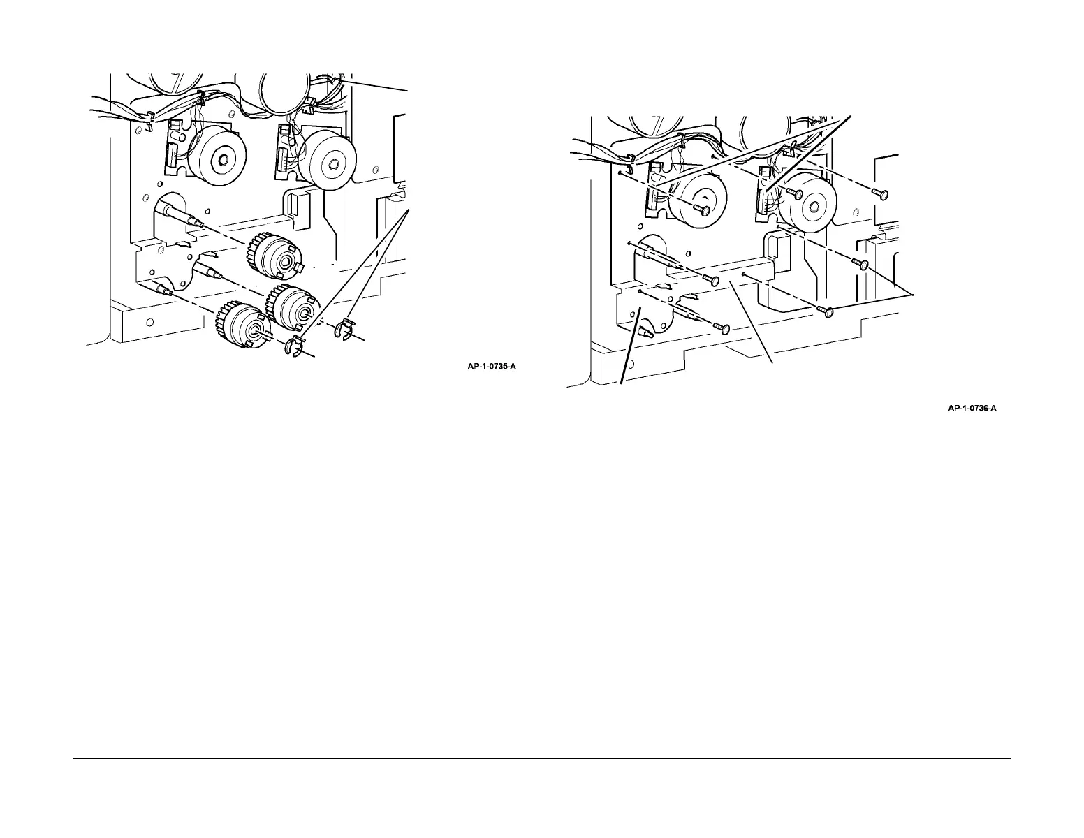
8. Remove the Main Drive Assembly (Figure 3).
NOTE: The position of each screw is numbered 1 to 7 on the Main Bracket. Remove the
screws in reverse numerical order.
Figure 3 Removing the Main Drive Assembly
Replacement
1. Replacement is the reverse of the removal procedure.
2. The 7 screws that secure the main drive assembly must be installed in numerical order.
1
Disconnect the 2-pin
inline connector.
2
Remove 2 KL-clips.
3
Remove 3 clutches.
1
Disconnect CN1.
3
Carefully remove the main drive
assembly.
2
Remove 7
screws (see
NOTE).
Main Bracket

 Loading...