MicroBlaze Processor Reference Guide 143
UG984 (v2018.2) June 21, 2018 www.xilinx.com
Chapter 3: MicroBlaze Signal Interface Description
IFetch
ILMB O
Instruction interface LMB instruction fetch
Instr[0:31]
ILMB I
Instruction interface LMB read data bus
IReady
ILMB I
Instruction interface LMB data ready
IWait
ILMB I
Instruction interface LMB data wait
ICE
ILMB I
Instruction interface LMB correctable error
IUE
ILMB I
Instruction interface LMB uncorrectable error
Mn_AXIS_TLAST
M0_AXIS..
M15_AXIS
O
Master interface output AXI4 channels write last
Mn_AXIS_TDATA
M0_AXIS..
M15_AXIS
O
Master interface output AXI4 channels write data
Mn_AXIS_TVALID
M0_AXIS..
M15_AXIS
O
Master interface output AXI4 channels write valid
Mn_AXIS_TREADY
M0_AXIS..
M15_AXIS
I
Master interface input AXI4 channels write ready
Sn_AXIS_TLAST
S0_AXIS..
S15_AXIS
I
Slave interface input AXI4 channels write last
Sn_AXIS_TDATA
S0_AXIS..
S15_AXIS
I
Slave interface input AXI4 channels write data
Sn_AXIS_TVALID
S0_AXIS..
S15_AXIS
I
Slave interface input AXI4 channels write valid
Sn_AXIS_TREADY
S0_AXIS..
S15_AXIS
O
Slave interface output AXI4 channels write ready
Interrupt
Core I
Interrupt. The signal is synchronized to Clk if the parameter
C_ASYNC_INTERRUPT is set.
Interrupt_Address
1
Core I
Interrupt vector address
Interrupt_Ack
1
Core O
Interrupt acknowledge
Reset
Core I
Core reset, active high. Should be held for at least 1 Clk clock
cycle.
Reset_Mode[0:1]
3
Core I
Reset mode. Sampled when Reset is active.
SeeTable 3-3 for details.
Clk
Core I
Clock
2
Ext_BRK
3
Core I
Break signal from MDM
Ext_NM_BRK
3
Core I
Non-maskable break signal from MDM
MB_Halted
3
Core O
Pipeline is halted, either using the Debug Interface, by setting
Dbg_Stop, or by setting Reset_Mode[0:1] to 10.
Dbg_Stop
3
Core I
Unconditionally force pipeline to halt as soon as possible. Rising-
edge detected pulse that should be held for at least 1 Clk clock
cycle. The signal only has any effect when
C_DEBUG_ENABLED
is greater than 0.
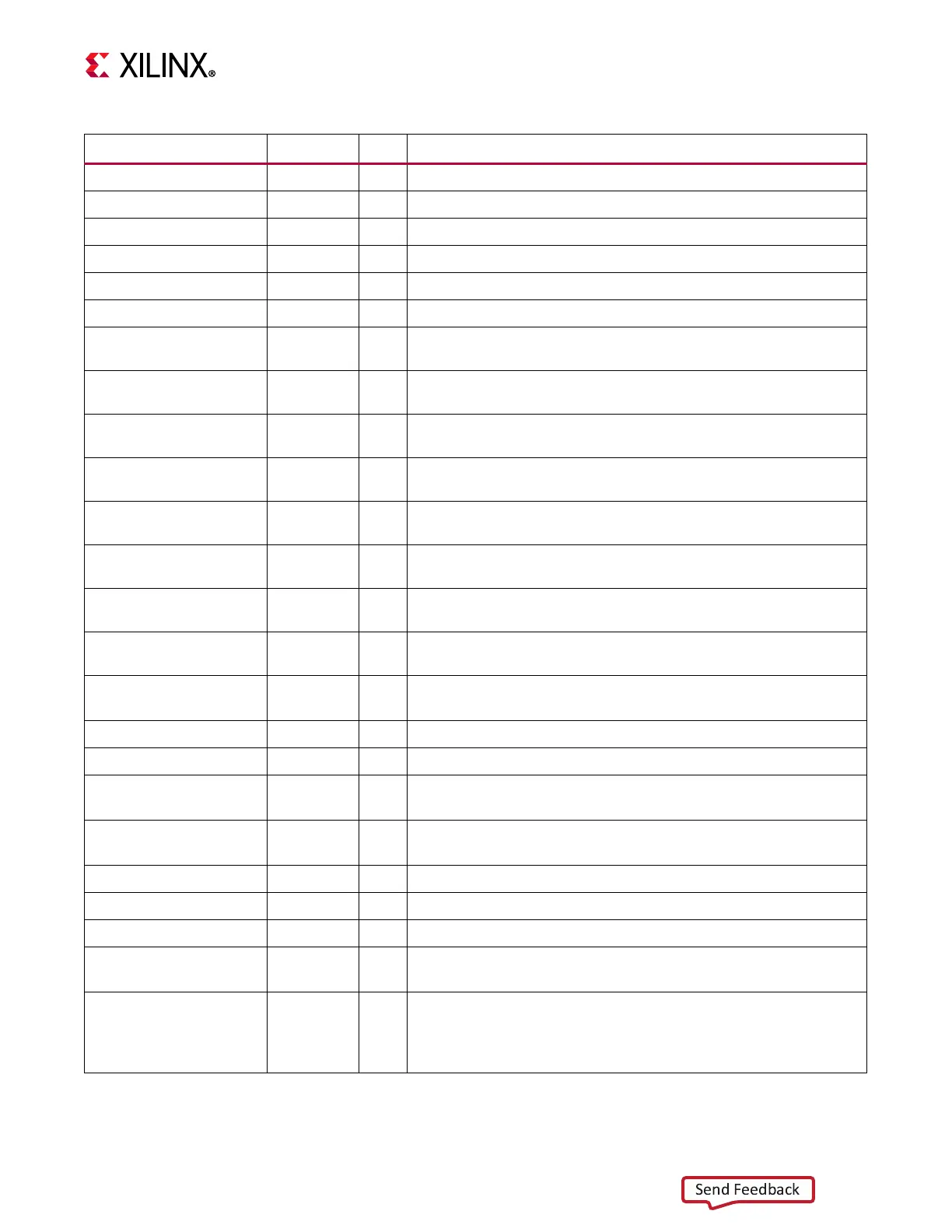
Table 3-1: Summary of MicroBlaze Core I/O (Cont’d)
Signal Interface I/O Description