E
HOW TO USE THIS MANUAL
1
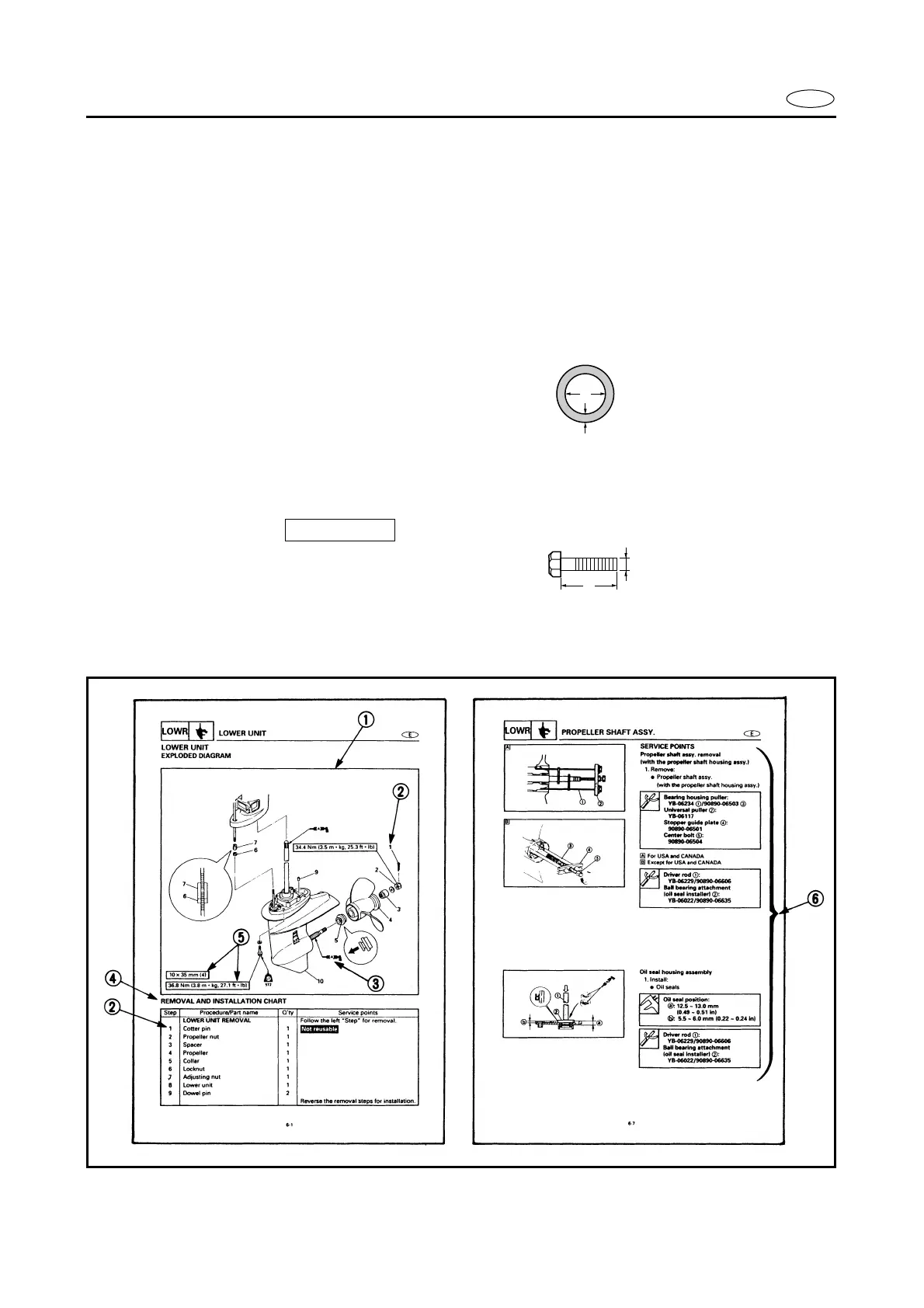
To help identify parts and clarify procedure steps, there are exploded diagrams at the start
of each removal and disassembly section.
2
Numbers are given in the order of the jobs in the exploded diagram.
3
Symbols indicate parts to be lubricated or replaced (see “SYMBOLS”).
4
A job instruction chart accompanies the exploded diagram, providing the order of jobs,
names of parts, notes in jobs, etc.
Example:
O-ring size 39.5
×
2.5 mm: Inside diameter (D)
×
Ring diameter (d)
5
Dimension figures and the number of parts, are provided for fasteners that require a tight-
ening torque.
Example:
Bolt or screw size : M10 (D)
×
25 mm (L)
6
Jobs requiring more information (such as special tools and technical data) are described
sequentially.
d
D
10 × 25 mm
D
L