5-11
E
POWR
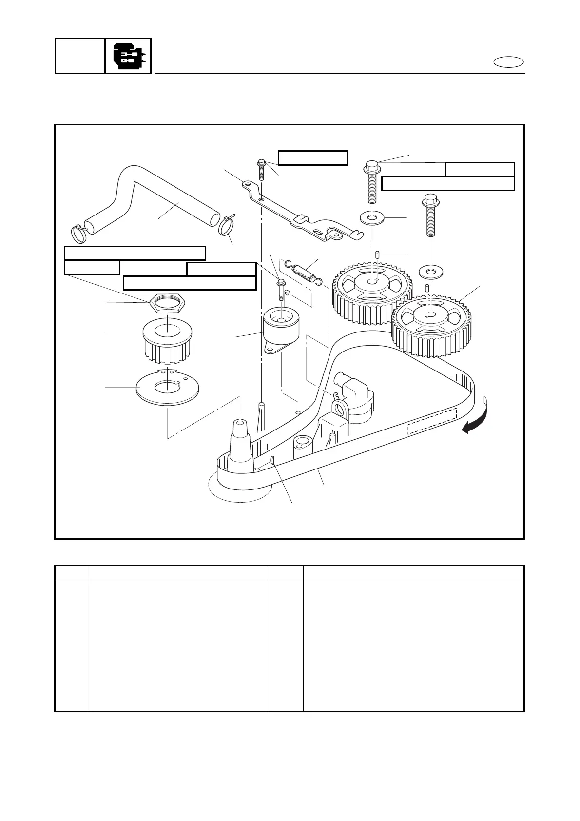
TIMING BELT
TIMING BELT
EXPLODED DIAGRAM
67F-46241-00
265 Nm (27 m
•
kg, 192 ft
•
Ib)
40 mm
40 Nm (4.0 m
•
kg, 29 ft
•
Ib)
10 × 45 mm
60 Nm (6.0 m
•
kg, 43 ft
•
Ib)
10 × 35 mm
6 × 30 mm
2
5
3
4
1
7
6
9
10
12
11
16
8
13
14
15
REMOVAL AND INSTALLATION CHART
Step Procedure/Part name Q’ty Service points
TIMING BELT REMOVAL
Follow the left “Step” for removal.
Stator coil assy. Refer to “STATOR COIL ASSY.”.
1 Bolt 2
2 Flywheel cover bracket 1
3 Bolt 1
4 Spring 1
5 Timing belt tensioner 1
6 Plastic band 2
7 Hose 1