5-31
E
POWR
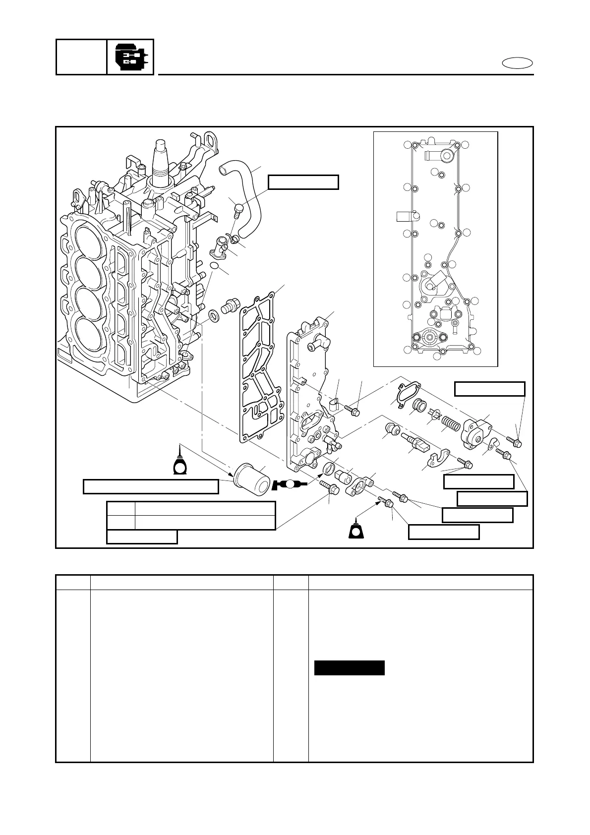
OIL FILTER AND EXHAUST COVER
OIL FILTER AND EXHAUST COVER
EXPLODED DIAGRAM
12
13
18
8
7
16
3
1
14
2
6
15 5
17
10
11
9
4
Å
E
1
7
20
26
25
24
12
14
15
11
17
22
19
21
18
23
16
10
8
9
6
5
4
3
6 Nm (0.6 m
•
kg, 4.3 ft
•
Ib)1st
12 Nm (1.2 m
•
kg, 8.7 ft
•
Ib)2nd
18 Nm (1.8 m
•
kg, 13 ft
•
Ib)
6 × 20 mm
13
6 × 16 mm
6 × 30 mm
6 × 20 mm
6 × 16 mm
8 × 25 mm
6 × 12 mm
LT
LT
572572
17
16
A
2
REMOVAL AND INSTALLATION CHART
Step Procedure/Part name Q’ty Service points
OIL FILTER AND EXHAUST
COVER REMOVAL
Follow the left “Step” for removal.
Camshafts and cylinder head
assy.
Refer to “CAMSHAFTS” and “CYLINDER
HEAD ASSY.”.
1 Oil filter 1
2 Plastic locking tie 1
3 Breather hose 1
4 Bolt 2
5 Breather hose joint 1
6 O-ring 1
7 Bolt 18 Refer to the illustration Å for the proper
tightening sequence.
Not reusable