3-11
INSP
ADJ
E
POWER UNIT
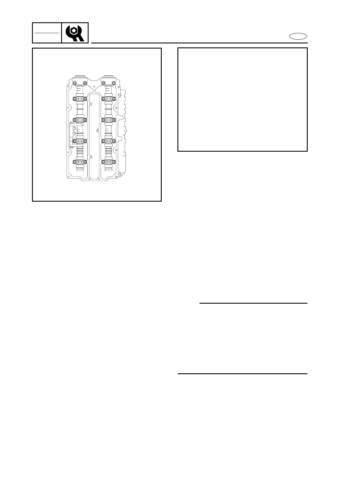
Measurement steps:
● Turn the flywheel magneto clockwise
until cylinder #1’s piston is at TDC.
● Measure the intake valve clearance for
cylinders #1and #2.
● Measure the exhaust valve clearance
for cylinders #1 and #3.
● Turn the flywheel magneto 360˚ clock-
wise.
● Measure the intake valve clearance for
cylinders #3 and #4.
● Measure the exhaust valve clearance
for cylinders #2 and #4.
IN EX
#1
#2
#3
#4
8. Loosen:
● Timing belt tensioner
9. Remove:
● Timing belt
● Driven sprockets
● Camshaft caps
● Camshafts
Refer to “POWER UNIT” in chapter 5.
10. Adjust:
● Valve clearance
NOTE:
● Do not mix the valve train parts (i.e., valve
pads, camshaft caps, camshafts). Keep
them organized in their proper groups
(e.g., cylinder #1 parts kept together).
● Install the removed parts in their original
positions. If valve train parts are installed
in the wrong position, proper valve
adjustments are impossible.