5.3 I/O Signal Connections
5-9
5.3 I/O Signal Connections
5.3.1 Connection Example of I/O Signal
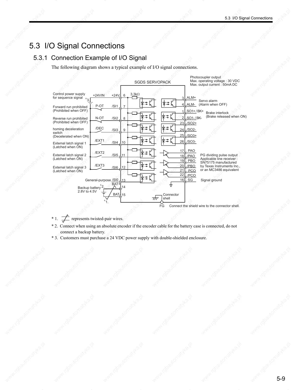
The following diagram shows a typical example of I/O signal connections.
* 1. represents twisted-pair wires.
* 2. Connect when using an absolute encoder if the encoder cable for the battery case is connected, do not
connect a backup battery.
* 3. Customers must purchase a 24 VDC power supply with double-shielded enclosure.
SO1+ / BK+
SO1- / BK-
/SO2+
/SO2-
/SO3+
ALM+
ALM-
FG
1
2
23
24
3
4
+24VIN
+24V
3.3kΩ
/SI1
/SI2
/SI3
/SI4
/SI5
6
8
10
9
11
12
/SI6
/SI0
P-OT
N-OT
/DEC
/EXT1
/EXT2
/EXT3
BAT+
BAT-
13
14
15
7
/SO3-
Control power supply
for sequence signal
Forward run prohibited
(Prohibited when OFF)
Reverse run prohibited
(Prohibited when OFF)
Extemal latch signal 1
(Latched when ON)
Extemal latch signal 2
(Latched when ON)
Extemal latch signal 3
(Latched when ON)
General-purpose
homing deceleration
switch
(Decelerated when ON)
Backup battery
2.8V to 4.5V
PG dividing pulse output
Applicable line receiver :
SN75175 manufactured
by Texas Instruments Inc.,
or an MC3486 equivalent
Photocoupler output
Max. operating voltage : 30 VDC
Max. output current : 50mA DC
Servo alarm
(Alarm when OFF)
Brake interlock
(Brake released when ON)
Signal ground
Connect the shield wire to the connector shell.
Connector
shell
SGDS SERVOPACK
PBO
PCO
/PBO
PAO
/PAO
/PCO
19
25
26
17
18
20
21
22
16
SG
∗
1.
∗
2.
∗
3.
 Loading...

